Operation
25
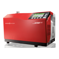
6.1.7 "Vacuum circuit" screen
Vacuum circuit of the detector and the status of the valves.
The vacuum circuit varies depending on the status of the valves, but does not make it
possible to manage the valves.
Fig. 7: Example of a vacuum circuit
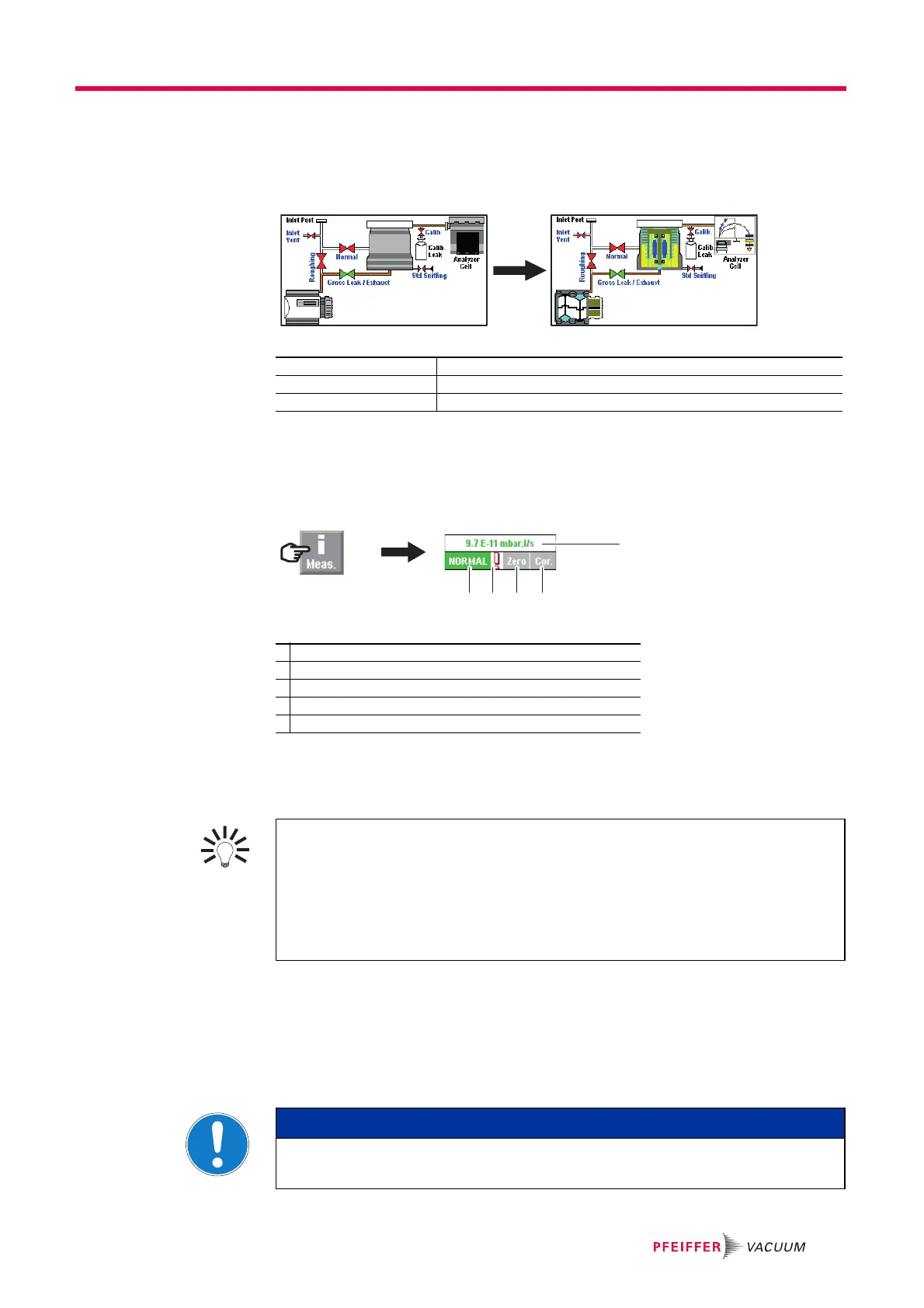
6.1.8 "Measurement" window
Press the [Measure] key to display the window.
Press and drag the window to move it on the screen.
Fig. 8: [Measure] key and corresponding window
6.1.9 Function keys
The function keys are used to activate/stop a function or to set set points (see 7.7.2).
6.2 Prerequisites to use
The following stages describe the use of the detector according to the initial settings
(see 7.2.1): the leak detector is set to perform a hard vacuum test in the most sensitive
test mode with a reject set point of 1·10
-8
Pa·m
3
/s (1·10
-7
mbar·l/s).
For use with any other parameters or other functions, see Chapter 7.
Red valve Valve closed
Green valve Valve open
Pumps, Analyzer cell Press the component to display the operating principle.
1 Digital display of the leak rate (green ≤ reject set point < red)
2 Detector test mode
3 Error information indicator
4 Zero function indicator
5 Leak rate correction function indicator
2 3 4 5
1
Thanks to the function keys, it is possible to give the operator access to a limited
number of functions and to use a password to lock unauthorised functions on the
"Settings" menu. they are sufficient to manage the detector.
To allow the operator to use only the [Start/Stand-By] key, do not allocate a function
to the function keys and lock the "Settings" menu.
Up to 4 additional function keys can be added, for a maximum of 12. In this case, a
3
rd
level is made available to the operator.
NOTICE
Wet Model: Filling with oil
Oil must be added to the primary pump before the detector is switched on.