Advanced settings
63
(1) Option or accessory
(2) With all I/O boards (option or accessory)
(3) With I/O Wi-Fi board (option or accessory)
(4) With I/O Ethernet board (option or accessory)
(5) Accessory
Parameters From the "Settings" screen, press [Advanced] [Input/Output] [Serial Link 1] or [Se-
rial Link 2] [Parameters].
Modes available depending on use.
(1) See Standard Remote Control Operating instructions for more details.
7.8.12 Input/Output: I/O connector
From the "Settings" screen, press [Advanced] [Input/Output] [I/O Connector].
The detector is equipped:
● either with a 15 pin I/O interface (see 15 pin I/O board Operating instructions).
● or, a 37 pin Input/Output interface (see 37 pin I/O board Operating instructions).
Wi-Fi
(3)
no yes Network
Ethernet
(4)
no yes Network
RC 500 WL remote
(5)
yes no Serial
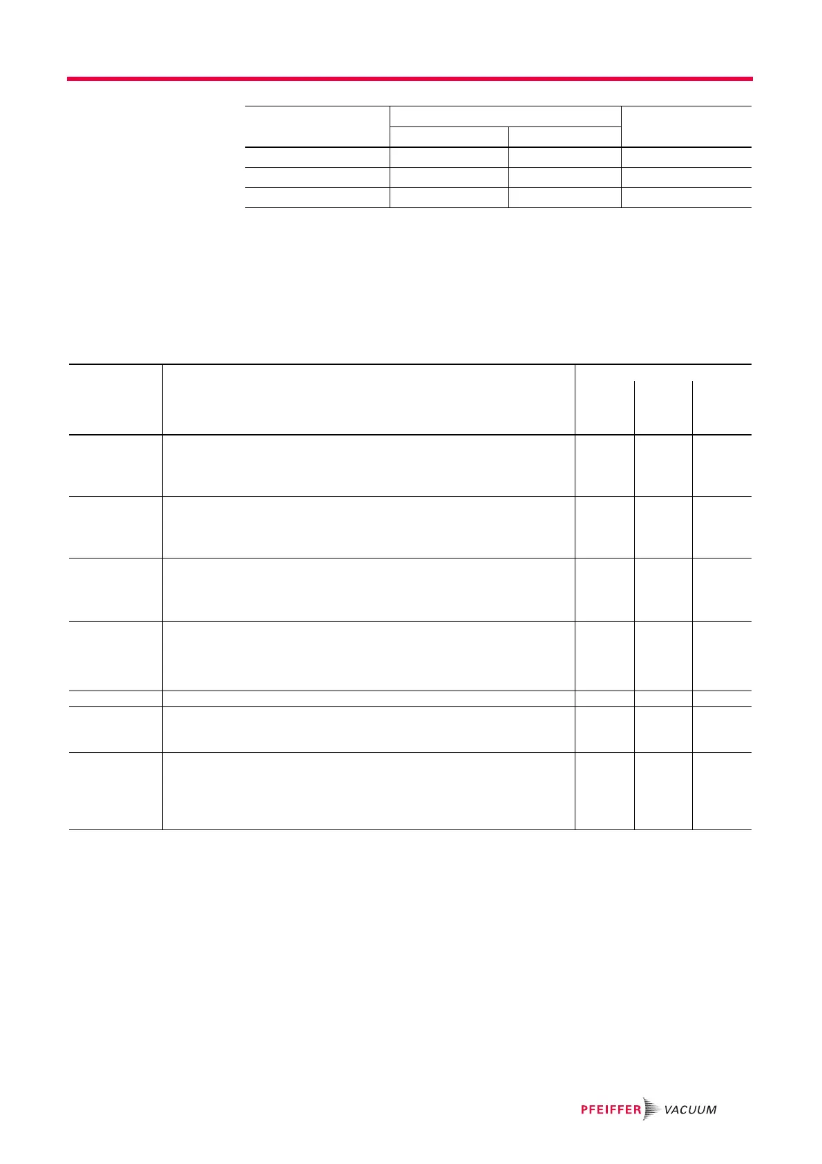
Use Possible allocation Type to select
Serial Link 1 Serial Link 2
Mode Description Use
(1)
RS 232 Blue-
tooth
USB /
Wi-Fi /
Ethernet
Basic (standard) Continuous acquisition of data sent to the hyperterminal according to a defined time
duration.
At any time, a command can be sent to the leak detector.
Recommended mode during leak detector test procedure setting operations.
xxx
Spreadsheet Variant on the Basic mode.
Continuous data acquisition, formatted in a spreadsheet such as Excel Microsoft
®
Office or other similar software.
Recommended mode for drawing graphs.
xxx
Advanced Full control of the detector by a supervisor.
The detector sends information at the supervisor's request.
5 V power supply available.
Recommended mode for automatic systems.
xxx
Export Data Export, via a PC, of "tickets" issued by the detector after:
• Calibration with an internal/external calibrated leak,
• Calibration control with an internal leak,
• A test.
Serial links 1 and 2 must not be in “Export Data” mode at the same time.
xxx
RC 500 WL Use of a wireless remote control (model RC 500 WL).
(1)
xx-
PV Protocol Protocol for compatibility with the HLTxxx detector protocol.
List of orders for the protocol compatible with ASM 340. See the RS 232 operating
instructions).
xxx
Ext. Module Full control of the detector by a supervisor.
The detector sends information at the supervisor's request.
24 V power supply available.
A 24 V power supply is required for using an external module (example: profi-
bus).
x- -