Advanced settings
42
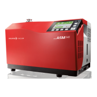
7.4.1 Test methods
There are 2 possible test methods (see 4.3):
● hard vacuum test,
● sniffing test.
Switching from ’Hard Vacuum test’ to ’Sniffing test’
After modifying the settings, a transition duration of < 3 min during which the test can be
performed but calibration is not possible.
Switching from ’Sniffing test’ to ’Hard Vacuum test’
After modifying the settings, a transition duration of 30 s during which neither the test nor
the calibration can be performed.
Fig. 21: "Method" screen using a function key
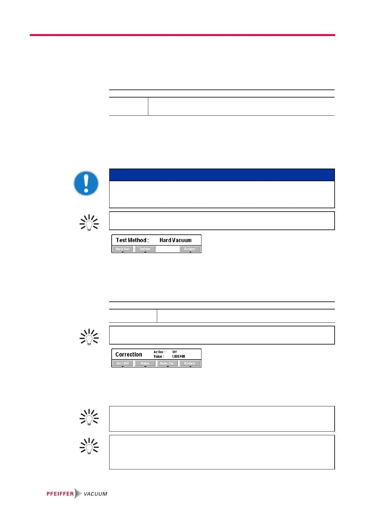
7.4.2 Correction factor
The correction factor allows correction of the measured leak rate by the detector when it
is combined to a pump.
Fig. 22: "Correction" screen using a function key
Displays: digital and
bargraph
Only the digital display is corrected by the correction factor: the correction factor does
not apply to the bargraph display.
From the "Settings" screen, press [Test].
Method Select the test method.
– For the hard vacuum test, set the test mode: (see 7.4.3)
– For the sniffing test, set the sniffing probe model used: (see 7.4.4)
NOTICE
Limit of operation
Make sure that the parts or chambers connected to the inlet of our products withstand
a negative pressure of 1 · 10
3
hPa in relation to atmospheric pressure.
For quick access from the control panel, set a function key for [Method] (see
7.7.2).
From the "Settings" screen, press [Test].
HV Correction/Sniff.
Correction
Activate the correction factor application.
Set the correction factor to be applied.
For quick access from the control panel, set a function key for [Correction]: (see
7.7.2).
Use the correction factor to work in a unit other than the one suggested ((see 11.3)
for the factor to be applied), if parallel pumping is installed, or if the Helium 4 used
is not 100 % Helium 4.
Depending on the concentration of tracer gas used for detecting leaks, the leak
rate displayed changes.
– Example: the leak rate displayed with a calibrated leak of 1·10
-8
Pa·m
3
/s
(1·10
-7
mbar·l/s) (with 100 %
4
He) connected to the detector's inlet.