Mixing pump G 4 X smart Overview - Operation and service
Description of assemblies
16 2021-08-12
11 Description of assemblies
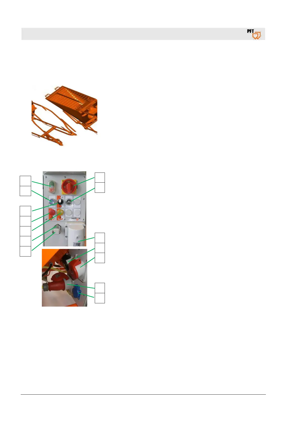
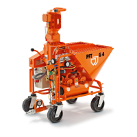
11.1 Hopper
Fig. 6: Assembly unit hopper
The mixing pump PFT G4 consists of the following main
components:
Hopper with frame and protective grille
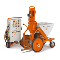
11.2 Control cabinet item number 00252527
Fig. 7: Assembly unit control cabinet
Control cabinet
1. Master switch is also emergency-stop switch
2. Push button water inlet
3. Main terminal 32A
4. CEE socket outlet 4x16A, controlled for water pump
5. CEE socket outlet 4x16A, for air compressor
6. CEE socket outlet 7x16A, for pump motor
7. Schuko socket outlet 230V, continuous current
8. Dummy connector for remote-controlled power socket
9. Remote control socket.
10. Yellow pilot lamp, for wrong direction of rotation
11. Red pilot lamp, motor protection switch was triggered
12. Selector switch star wheel
13. Push button reverse direction of rotation
14. Operating button machine “ON” / “OFF” (control voltage)
1
2
3
4
5
6
7
14
13
12
11
10
9
8