Mixing pump G 4 X smart Overview - Operation and service
Description of assemblies
2021-08-12 17
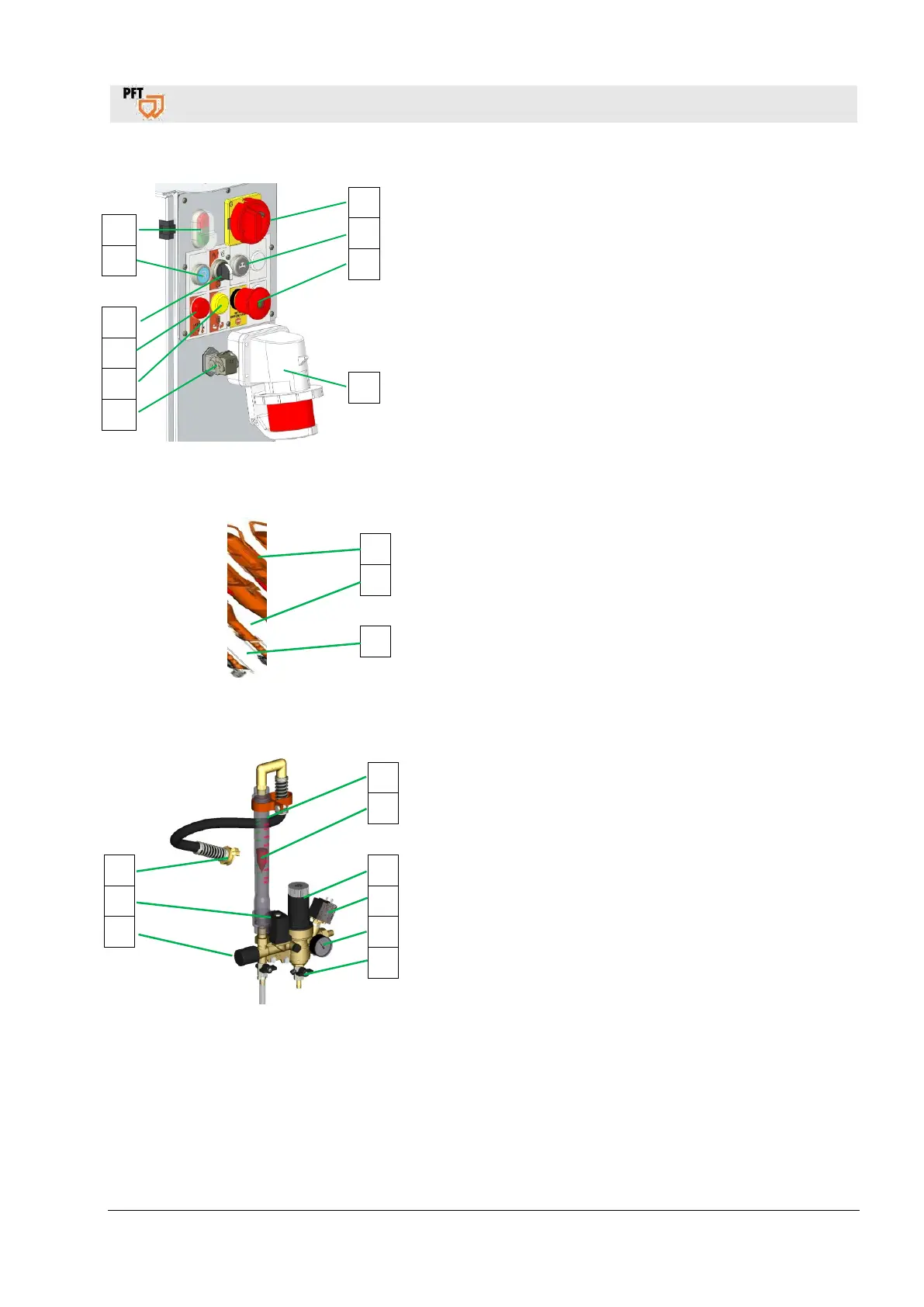
11.3 Schaltschrank Artikelnummer 00671960
Abb. 8: Baugruppe Schaltschrank
Schaltschrank
1. Hauptwendeschalter, ist gleichzeitig Not-Aus-Schalter
2. Drucktaster Wasservorlauf
3. NOT-HALT-Drucktaster
4. Hauptstromanschluss 32A
5. Blindstecker für Fernsteuersteckdose
6. Kontrolllampe gelb, für falsche Drehrichtung
7. Kontrolllampe rot, Motorschutzschalter hat ausgelöst
8. Wahlschalter Zellenrad
9. Drucktaster Drehrichtung rückwärts
10. Betriebstaster Maschine „EIN“ / „AUS“ (Steuerspannung)
11.4 Mixing tube with motor and pump
Fig. 9: Assembly unit mixing tube with motor
1. Pump motor 5.5kW
Pump motor 4kW
2. Mixing tube G 4 X without adaptable flange
Mixing tube G 4 X with adaptable flange
3. Pump unit D6-3
Pump unit D5-2.5
Pump unit D8-2
11.5 Water tap
Fig. 10: Water tap assembly
1. Water flow meter 100-1000l/h
2. The floater shows the set water factor on the scale of the
plastic tube
3. The water pressure can be adjusted at the pressure reducer
4. Pressure switch water shuts down the machine in case the
water pressure is too low
5. Pressure gauge water / operating pressure
6. Drain tap for frost protection
7. The required water factor is set at the needle valve
8. Solenoid valve
9. Water to mixing tube
1
2
3
3
10
9
8
7
6
5
1
2
3
1
2
3
4
5
6
9
8
7