Mechanical Instructions
EN 47DVDR70 & DVDR75/0x1 4.
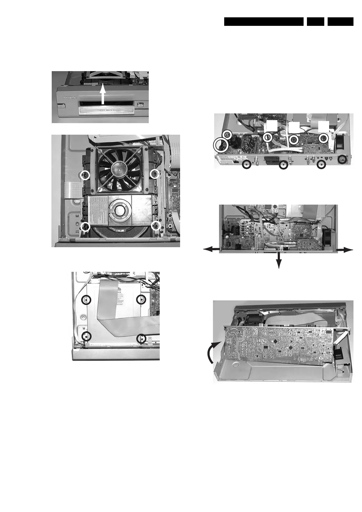
4.1.5 Basic Engine
– Remove the tray (1)
– Remove the four screws that fix the drive, see figure 4-6 or
4-7
Figure 4-6
Figure 4-7
4.1.6 Analog Board
– Remove the 3 screws (1) that fix the back plate to the
bottom plate, see picture 4-8
– Remove the 4 screws (2) that fix the Analog Board to the
bottom plate
– In sets with fan remove the Fan assy by releasing the fixing
screw (3)
– Remove screw safety holder (4)
– Unlock the two snaps hooks at the left and right (5), see
picture 4-9, and pull the board and backplate out gently (6)
– Turn the PCB in the service position (7), see picture 4-10
Figure 4-8
Figure 4-9
Figure 4-10
1
2
2
2
2
1
1
1
2
2
2
2
3
4
5
5
6
7