Circuit-, IC descriptions and list of abbreviations
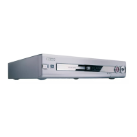
EN 184 DVDR70 & DVDR75/0x19.
9.5.10 Progressive Scan
Description
The progressive scan part is integrated in the Digital Board and
built around the SAGE Fli2200 de-interlacer / line doubler
(7701). This I2C controlled de-interlacer uses a 64Mbit SDRAM
(32bit x 2M) to perform high quality deinterlacing (meshing).
The de-interlacer gets his digital YUV input data from the
STi5508 (7200). The format of the digital YUV input to the
SAGE is CCIR656 with separated Hsync, Vsync and odd/even
signal running on 27Mhz.
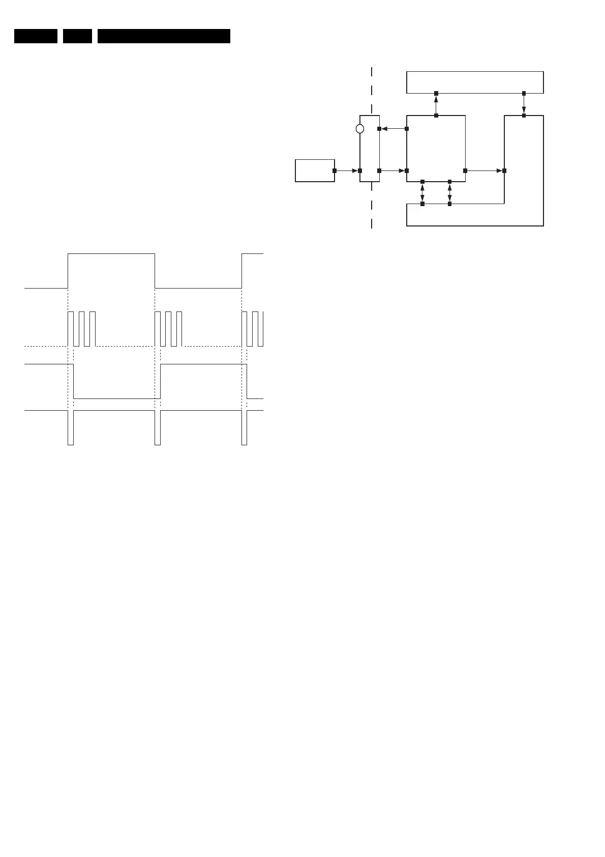
Because the STi5508 doesn't have a Vsync output the odd/
even output of this IC has to be translated to a Vsync signal.
Some glue logic has been added to extract the vertical sync.
The glue logic circuit consists of Flip-Flop IC 74HC74D (7701)
and EXOR 74LVC86 (7702). The next diagram shows how the
vertical sync is extracted.
Vertical Sync
Figure 9-5
The output of the de-interlacer (4:4:4 progressive video) is fed
to the Analog Devices ADV71967 MacroVision compliant
DENC (7801).
The YUV current output of the DENC is fed via a low pass filter
to the single supply output opamps AD8061/8062 (7802-7803).
The analog video is fed via a 7 poled flex to the analog board
where the YUV 2FH cinch connectors are located.
9.6 Divio 1.8 Board
9.6.1 Short Description of the Module:
The DVIO Module is a decoder for DV streams. Input is a
stream from a DV-camcorder via IEEE1394. Outputs are
CCIR656 Video and Analog audio (L+R). A serial control
interface is present.
The following picture shows the location of the DVIO Module
inside the DVDR set.
Description DIVIO Module
Figure 9-6
FRAME_IN
(odd/even)
HS_IN
VS_IN
pin 6 IC7102
CL 16532095_123.eps
150801
camcorder
Front DV PCB
On/Off
IEEE1394
IEEE1394
Analog
audio L+R
Digital
Audio I2S
Digital video
CCIR656
Control RS232Control Misc.
LED
DVIO Module
ADC (analog PCB)
Audio
Encoder
(dig. PCB)
Video
Encoder
(dig. PCB)
Host decoder STi5505
(dig. PCB)
CL 16532095_118.eps
150801