Diagnostic Software
EN 49DVDR70 & DVDR75/0x1 5.
5. Diagnostic Software
Due to the complexity of the DVD recorder, the time to find a
defect in the recorder can become long. To reduce this time,
the recorder has been equipped with Diagnostic and Service
software (DS). The DS offers functionality to diagnose the
DVDR hardware and tests the following:
• Interconnections between components
• Accessibility of components
• Functionality of the audio and video paths
This functionality can be accessed via several interfaces:
1. End user/Dealer script interface
2. Command Interface
3. Player script interface for sets with Digital Board 1.5,
Empress
4. Menu interface for sets with Digital Board 1.5, Empress
5.1 End User/Dealer Script Interface
5.1.1 Description
The End user/Dealer script interface gives a diagnosis on a
stand alone DVD recorder. During this mode, a number of
hardware tests (nuclei) are automatically executed to check if
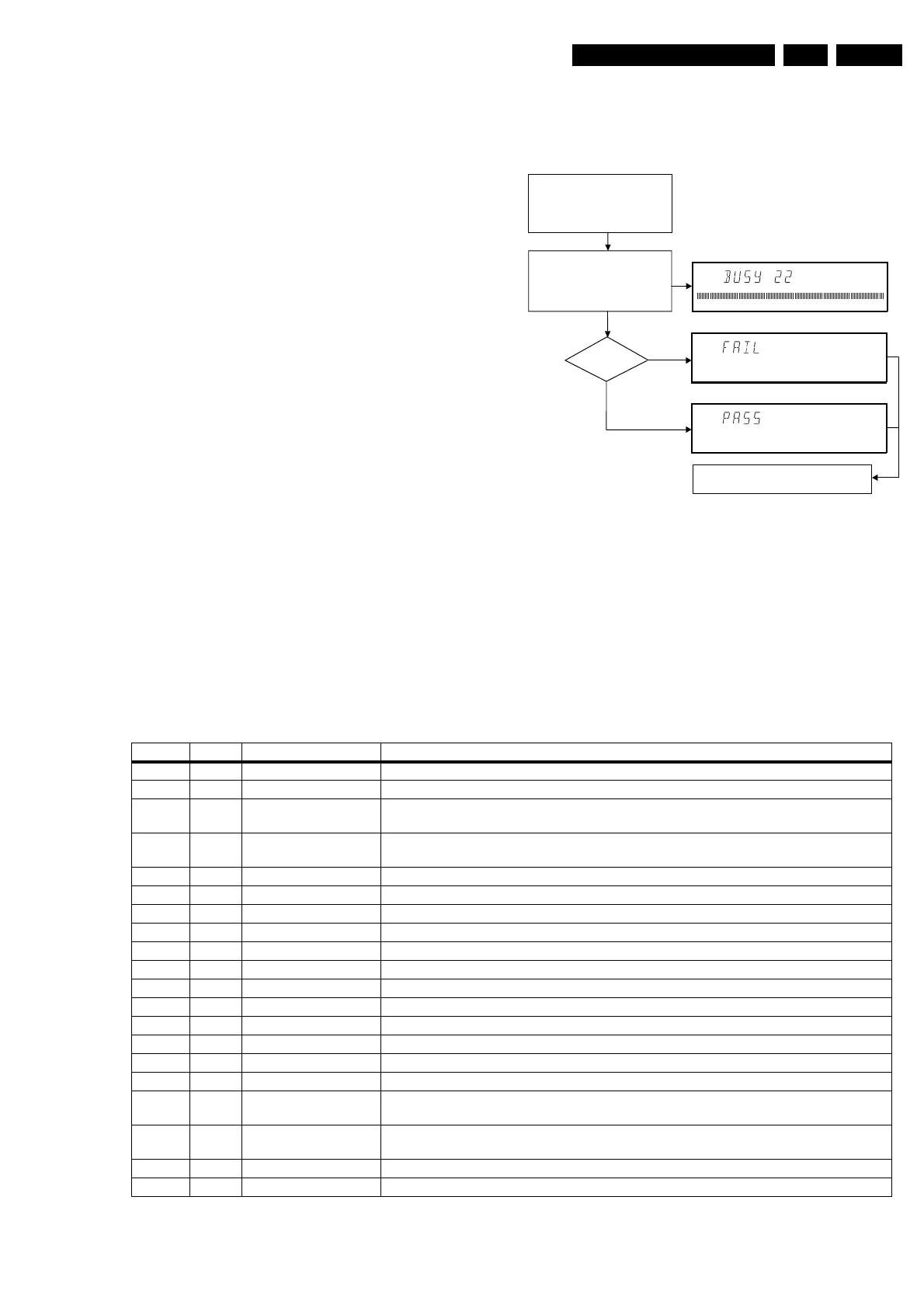
the recorder is faulty. The diagnosis is simply a "fail" or "pass"
message. If the message "FAIL" appears on the display, there
is apparently a failure in the recorder. If the message "PASS"
appears, the nuclei in this mode have been executed
successfully. There can be still a failure in the recorder
because the nuclei in this mode don't cover the complete
functionality of the recorder.
5.1.2 Structure
Figure 5-1
The End use/Dealer script executes all diagnostic nuclei that
do not need any user interaction and are meaningful on a
standalone DVD recorder.
5.1.3 Contents for sets with Digital Board 1.5, Empress
The nuclei called in the End user/Dealer script are the
following:
Hold key <PLAY> pressed
while you plug the recorder
Unplug the power cord
During the test, the following display
is shown: the counter counts down
from the number of nuclei to be run
before the test finishes. Example:
SET O.K.?
YES
NO
To exit DEALER SCRIPT, unplug the power cord
CL 16532095_068.eps
150801
Counter Nucleus Name Description
22 104 HostdSdramWrR checks all memory locations of the 4MB SDRAM
21 106 HostdDramWrR checks all the DRAM connected to the microprocessor of the digital board
20 123 HostdI2cNvram checks the data line (SDA) and the clock line (SCL) of the I2C bus between the host decoder
and NVRAM
19 202 SAA7118I2c checks the interface between the Host I2C controller and the AVENC SAA7118 Video Input
Processor
18 200 VideoEncI2c checks the interface between the host I2C controller and Empress SAA6752
17 207 AudioEncI2c checks the I2C connection between the host decoder and Empress SAA6752
16 204 AudioEncAccess tests the HIO8 interface lines between the host decoder and the audio encoder
15 203 AudioEncSramAccess checks the access of the SRAM by the audio encoder (address and data lines).
14 205 AudioEncSramWrR tests the SRAM connected to the audio encoder
13 206 AudioEncInterrupt tests the interrupt line between the host decoder and the audio encoder
12 300 VsmAccess checks whether the VSM interrupt controllers and DRAM are accessible
11 303 VsmInterrupt checks both interrupt lines between the VSM and the host decoder
10 302 VsmSdramWrR tests the entire SDRAM of the VSM
9 1400 Clock11_289MHz switches the A_CLK of the micro clock to 11.2896 MHz
8 1401 Clock12_288MHz switches the A_CLK of the micro clock to 12.288 MHz
7 601 BeS2Bengine checks the S2B interface with the Basic Engine by sending an echo command
6 500 DisplayEcho checks the interface between the host processor and the slave processor on the display
board
5 700 AnalogueEcho checks the interface between the host processor and the microprocessor on the analogue
board
4 711 AnalogueNvram checks the NVRAM on the analogue board
3 706 AnalogueTuner checks whether the tuner on the analogue board is accessible