Circuit-, IC descriptions and list of abbreviations
EN 188 DVDR70 & DVDR75/0x19.
9.7.3 Playback Mode
During playback, the serial data from the Basic Engine is going
directly to the PNX7100 via the serial front-end I2S interface.
The PNX7100 is an MPEG CoDec and has the following
outputs:
• To the analogue board: analogue video RGB, YC, CVBS
on connector 1904.
• I2S audio (PCM format) on connector 1900.
• SPDIF audio (digital audio output) on connector 1904.
• Progressive video on connector 1704.
• Communication gateway (RS232) on connector 1104.
9.7.4 Basic Engine Interfaces
AV2 Basic Engine (VAE8015 and VAE8020)
The UART interface (for the S2B commands) between the
Chrysalis and the servo processor (MACE3 on the BE module),
controls the AV2 Basic Engine during record and playback
mode. For data transport, an I2S bus is used.
For detailed information on the AV2 BE module, see Service
Manual 3122 785 12470.
AV3 Basic Engine (VAE8030)
To be prepared for new developments, the Chrysalis Digital
Board is equipped with two IDE busses (ATAPI). They can be
used for connecting to the new generation Basic Engine (e.g.
the AV3), a Hard Disc Drive (HDD), or a Smart Card Reader.
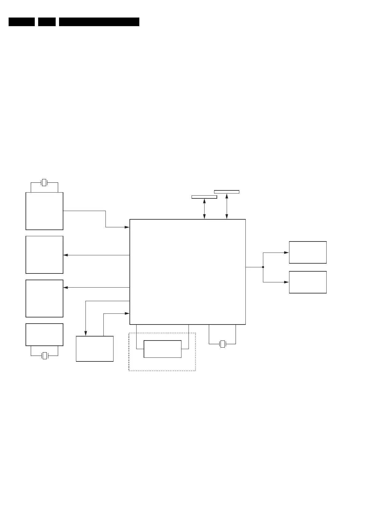
9.7.5 Clock Distribution
Clock distribution on Chrysalis board
Figure 9-10
The PNX7100 has a complex clock system, which is needed to
support the processes running at different frequencies such as
video decoding, audio decoding or peripheral I/O devices etc.
To ensure a synchronous initialisation of all the registers and
state machines, all the PLLs are switched to their default
frequency and the reset sequence is run at 4 MHz. Then when
the booting control unit is correctly initialized and once it has
captured all the booting parameters, it sets the PLLs to its
functional frequency to allow the modules to run at their
nominal frequencies. Thanks to a clock blocking mechanism,
the frequency switching is glitch free.
System clocks:
• PNX7100 (IC7400, pins AF9 and AF10) : 4 MHz provided
by the xtal oscillator 7402.
• SAA7118 (IC7004, pins A3 and B4): 24.576 MHz provided
by xtal 1001.
• ADV7196 (IC7703, pin 25): 27 MHz provided by PNX7100.
• SDRAM (IC7804 and 7808, pin 38): 133 MHz provided by
the PNX7100.
• 1394-LINK (IC7201, pin 88): 49.152 MHz provided by
1394-PHY.
• 1394-PHY (IC7200, pins 59 and 60): 24.576 MHz provided
by xtal 1201.
VIP7118
7004
ADV7196
CHRYSALIS
PNX7100
7703
7400
SDRAM
BE INTERFACE
7804
133MHz
SDRAM
7812
1394 LINK
7201
AUDIO PLL
27 MHz
Osc.
7300
OPTIONAL
1394 PHY
24.576 MHz
24.576 MHz
7200
4 MHz
CL 36532004_004.eps
140203