Mechanical Instructions
EN 48 DVDR70 & DVDR75/0x14.
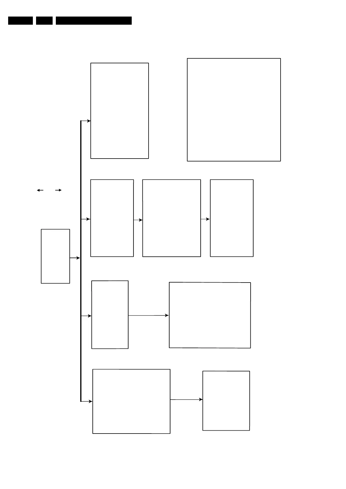
4.2 Dismantling Instructions
Figure 4-11
DISMANTLING INSTRUCTIONS
See exploded view for item numbers
Front assy
⇒
⇒
remove 3 screws 205
(front assy
→
frame 100)
⇒
unlock the front from the
frame by releasing 2 snaps
on left and right
mounting
demounting
Cover 300
⇒
Remove 9 screws 298
⇒
Lift the cover
Analog board 1001
⇒
⇒
demount the board
remove screw safety
holder 145
→
→
→
demount the board carefully.
(board to board connection to
the Digital board)
DVIO board 1003
⇒
⇒
⇒
DVDR BASIC ENGINE 1007
Manual opening of tray and removal of
In case the loader is defective and cannot be
opened electrically, you can open the tray
as follows:
⇒
⇒
Open the tray and remove
the tray front 70
⇒
Remove the connections
⇒ Remove the connections
Display board 1004
⇒
⇒
Remove screws
200
→
demount the board
open the tray and remove
tray front 70
Remove 4 screws 255
(Basic Engine 1007
support bracket 160)
Remove 2 screws 216
Release the snaps of 2 spacers 125
(DVIO board Digital board)
(DVIO board bracket 161)
(board
front)
→
demount the board.
Digital board 1002
⇒
⇒
Remove 4 screws 214
(Digital board frame 100)
to remove
the
⇒
Demount the DVDR Basic Engine
Open the unlocked tray.
It is possible to unlock the tray by means
of a screwdriver via a slot in the
front and frame at the underside.
.
⇒
⇒
Push the white pin of the slider at the
underside of the basic engine to the right
(seen from the front)
⇒ remove 4 screws 210
(board frame)
→
⇒ remove 11 screws 230, 231
(board backplate)
⇒
Remove the connections
→
⇒ remove 3 screws 250
(frame backplate)
→
tray front 70
⇒
remove 9 screws 200 to
remove the plate front 102
⇒
Remove screws 209
of DV input cable
→
demount the board
IOE board 1005
⇒
⇒
Remove 2 screws 234, 235
(IOE board
frame 100)
→
demount the board.
EPG board 1006
⇒
⇒
Remove 2 screws 218
(Digital board bracket 161)
⇒
Release the snaps of 2 spacers 130
(DVIO board EPG board)
→
TR 06003_001
300103