Circuit-, IC descriptions and list of abbreviations
EN 189DVDR70 & DVDR75/0x1 9.
9.7.6 Power Supply
The Digital Board is not powered in standby mode. The control
signal 'ION' (Inverse On), coming from the analogue board, will
enable the PSU, and power the digital board.
• ION = High: the digital board is in powered down standby
mode.
• ION = Low: the power supply to the digital board is
enabled.
The 3V3, +5V, -5V, and +12V come from the PSU, while the
1V8 core voltage is generated on the board by a low voltage
buck controller (item 7501). It provides the control for a DC-DC
power solution producing an 1.8V output voltage over a wide
current range. The NCP1570-based solution is powered from
12 V with the output derived from the 3V3 supply. It contains all
required circuitry for a synchronous NFET (IC7500-1 and -2)
buck regulator.
9.7.7 Memory
Several memories are used on the Chrysalis Digital Board:
• EEPROM IC7810: this memory contains all the necessary
boot parameters of the board.
• EEPROM IC7809: this memory contains all the necessary
parameters for the application.
• FLASH IC7807(05/11): this memory contains the
application-, diagnosis-, and service software.
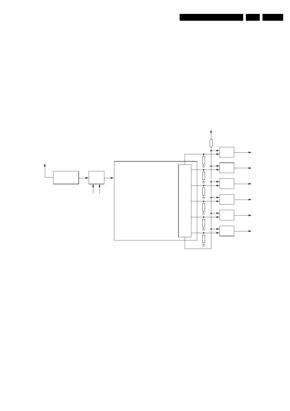
9.7.8 Reset
Reset concept Chrysalis board
Figure 9-11
The voltage detector NCP303LSN29 (IC7600) provides the
reset signal PNX7100_RESETn (active 'low') with the correct
timing behavior. This circuitry functions as a Power-On Reset
(POR) module, which detects the minimum functional voltage
that is needed by the device. It also detects any voltage drop.
When the power voltage is outside the nominal range, a reset
signal is generated by the POR module and fed to the reset
module which controls the individual reset of the different
peripherals and processing units.
There are two control lines which can overrule this reset signal:
• IRESET_DIG (controlled by the microprocessor on the
Analogue Board).
• EJTAG_RESETn (only for production).
They can pull the output of the NCP303LSN29 (item 7106)
down via a shottky diode.
So when the output signal PNX7100_RESETn is 'low', the
board will reset. When this signal is 'high', the board is up and
running.
The PNX7100_SYS_RESETn is a general enabling signal for
the different reset lines. All other reset lines are directly driven
from Chrysalis port pins (e.g. MPIO13_IDE1_RESETn). All
reset lines are logically connected via 74LVC08D (item 7104)
and (item 7107) AND-gates. If both reset signals are low, all
other external devices are initialised.
9.7.9 I2C Bus
The PNX7100 is the master of the I2C bus (during reset,
external I2C masters are allowed). The following ICs are
controlled by the I2C bus:
• IC7809.
• IC7810 NVRAMs.
• IC7004 VIP.
• IC7700 FLI2301 Video De-interlacer Line Doubler (for
Chrysalis-F boards).
• IC7703 ADV7196 Video Enc (for progressive scan done by
Chrysalis).
9.7.10 I/O Connectors
AIO Connector (item 1900)
The Audio In/Out (AIO) connector is used to interchange digital
audio signals between Analog- and Digital Board.
CHRYSALIS
PNX7100
7400
GPIO
7104-3
&
Reset_IDEn
PNX7100_Resetn
PNX7100_SYS_Resetn
7106
3V3
>1
EJTAG_Resetn
IResetDig
NCP303
7104-4
&
Reset_1394n
7107-1
&
Reset_BEn
7107-2
&
Reset_PSn
7107-3
&
Analog_Resetn
7104-1
&
VIP_Resetn
3V3
CL 36532004_005.eps
140203