Description of the controllers
107708_en_08 PHOENIX CONTACT 29 / 112
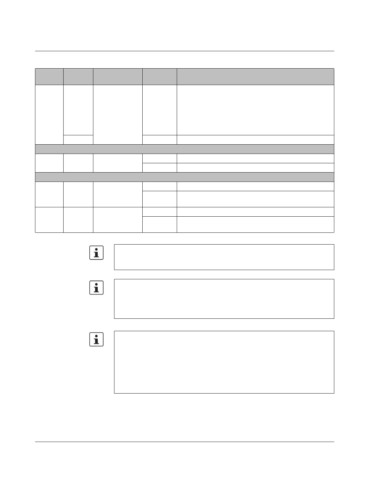
EXT
Red
Left alignment
On
Error at extension module
Possible error causes:
– Extension module is not supported.
– Extension module is not mounted correctly or is defective.
– Extension module was disconnected from power during
operation or has been removed.
Green On Extension module operating without errors.
PWR: Supply voltage (communications voltage U
L
)
UL Green U
Logic
Off 24 V communications voltage feed-in not present or too low
On 24 V communications voltage feed-in present
ETH: Ethernet interfaces
Green Link status
Off Connection not established successfully
On
Connection established successfully (link): The controller is
able to contact another network device.
Yellow Activity status
Off Data transmission not active
On/flashing
Data transmission active (activity): The Ethernet interface is
sending or receiving data.
Table 3-1 Controller diagnostic and status indicators
Desig-
nation
Color Meaning State Description
Please note:
On the AXC F 1152, the EXT LED is without function as Axioline F extension modules
cannot be aligned to the left.
Special case: firmware update
During a firmware update, the RUN LED first flashes, and then stops. Upon a successful
controller restart, the RUN LED lights up again permanently.
Information on firmware updates can be found in Section “Replacing the HTTPS certifi-
cate” on page 102.
Special cases: SD card
– Unauthorized removal of the SD card during operation:
If the SD card is removed during operation, all LEDs except the D and E LEDs begin
to flash red (1 Hz).
– Invalid SD card license:
If the SD card is invalid, all LEDs except the D and E LEDs begin to flash red (1 Hz).
Information on operating the controller with an SD card can be found in Section “SD card
(optional)” on page 33.
 Loading...


