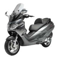
2-FLASH CODE - Example with programmed control unit, no transponder and/or malfunctioning aerial.
Ignition disabled-Vehicle immobilised
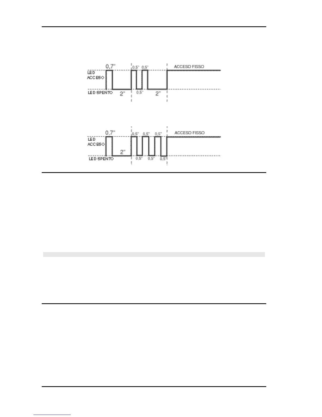
3-FLASH CODE - Example with programmed control unit, aerial working properly and unknown trans-
ponder code. Ignition disabled-Vehicle immobilised
Diagnostic code - 2 flashes
Diagnosis code: 2-flashes
When the 2-flash code is detected, carry out the following checks:
- Check if the failure continues after changing key (MASTER key included). If the failure persists with
any key, disconnect the aerial connector from the control unit and check the aerial continuity with the
020331Y multimeter.
If non-conforming values are measured, replace the aerial.
If no failures are found in the aerial, replace the control unit.
CAUTION
BEFORE PROGRAMMING THE NEW ELECTRONIC CONTROL UNIT CHECK THAT NO FAILURE
CODE IS INDICATED. THIS IS NECESSARY TO AVOID SPOILING A NEW CONTROL UNIT
Electric characteristic
immobilizer aerial
~ 7 ÷ 9 Ohm
Ignition circuit
Once the immobilizer system is enabled, the HV coil and the signals from the Pick-Up will produce a
spark in the spark plug.
The battery provides the basic power supply. The system is adjusted so that the start-up system im-
mediately detects an eventual battery voltage drop, but this is practically irrelevant for the ignition
system.
The Pick-Up is connected to the control unit by a single cable; then, for the ground circuit, the control
unit is connected to the Pick-Up by the chassis and the engine ground lead.
Electrical system MP3 125
ELE SYS - 14