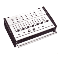
Tie the D-OUT cables
with the PCB binder.
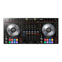
Pass the D-OUT cables through the
clamp that has been attached to
the board.
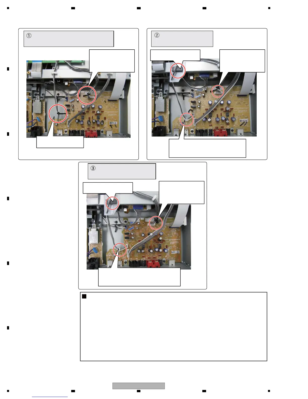
Fix the D-OUT cables with the Locking
Mini Clamp that has been inserted in
the hole of the board.
Tie the cables for
analog signals
with the PCB binder
located on the left.
Tie the cables for
analog signals
with the PCB binder
located on the left.
Tie the cables for
analog signals
with the PCB binder
located on the right.
Add the Shield Sheet
and FFC guard.
Add the Shield Sheet
and FFC guard.
: Initial dressing
(for the DWX2710 and DWX2896)
: Temporary dressing
(for the DWX2896)
: Permanent dressing
(for the DWX2896)
[3] Differences in Cable Dressing States
Notes
1: Before replacing the Assy, be sure to check the current cable dressing.
2: Depending on the dressing state, some additional parts may be required:
If the previous board is in the initial cable dressing state:
FFC guard (DEC2586), Shield Sheet (DEC3151) and Locking Mini Clamp (DEC2439)
If the previous board is in the temporary cable dressing state:
Locking Mini Clamp (DEC2439)
If the previous board is in the permanent cable dressing state:
No additional parts needed
3: Permanent cable dressing is possible with the Assy for service.
 Loading...