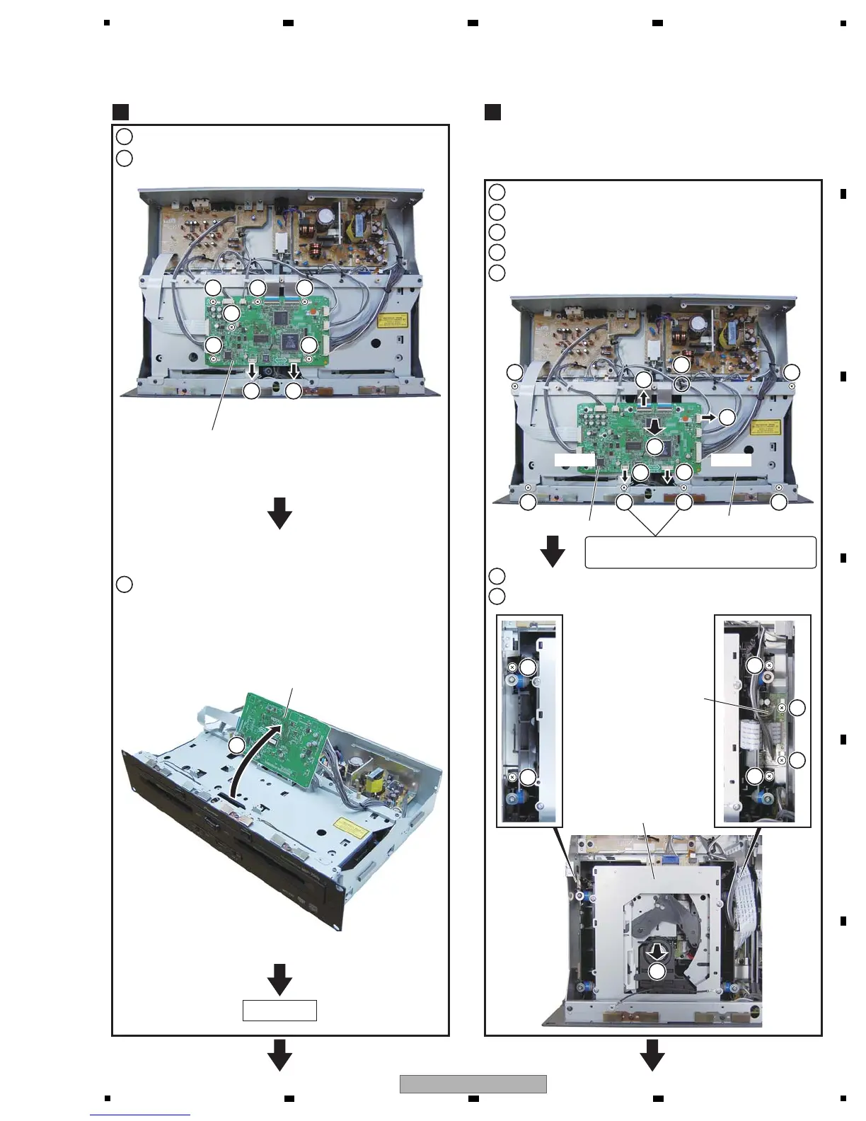
SMAIN Assy
SRV1 Assy
Drive Section
Diagnosis of the SMAIN Assy
Release the two jumper wires.
Release the two jumper wires.
Remove the six screws.
1
Lift the SMAIN Assy.
2
6
6
6
6
6
6
Drive Section
2
Remove the six screws.
1
Disconnect the flexible cable and connectors.
2
Release the jumper wire.
3
Remove the PCB stay Assy with the SMAIN Assy.
4
Remove the six screws.
6
5
Remove the Drive Section.
7
Note:
The procedure to show below is only DISC 1 side.
As for DISC 2 side, the procedure is the same.
7
Diagnosis
SMAIN Assy
2 2 2
22
2
11
3
3
DISC 2DISC 1
SMAIN Assy
PCB Stay Assy
2 2
2222
1
1
3
3
4
5
Note: When tightening the screws,
tighten the grounding lead unit together.
 Loading...