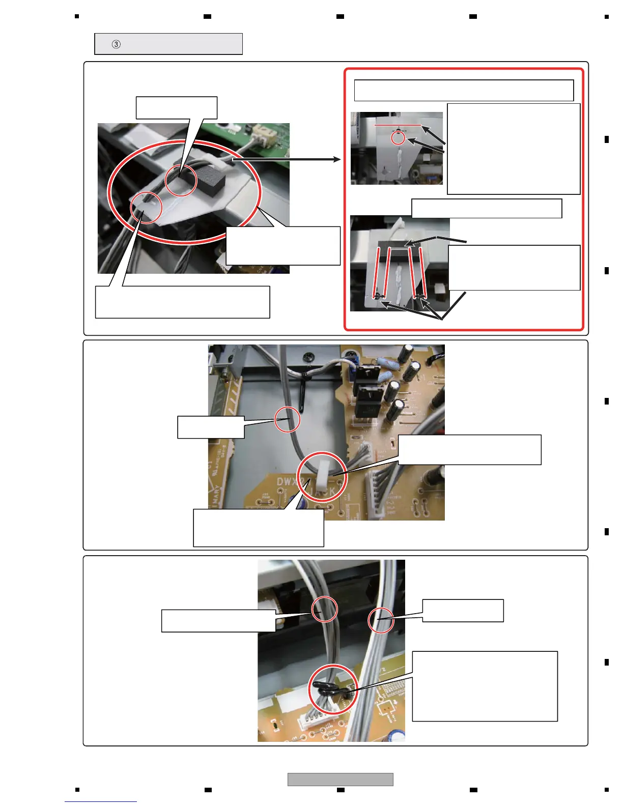
Fig : Permanent cable dressing
Insert the locking mini clamp
(DEC2439, additional part)
in the hole of the board.
D-OUT cables
Cables for analog signals
Pass the D-OUT cables
through the locking mini clamp.
Tie the cables for analog signals
with the PCB binder at the base.
Push the cables down toward
the board so that they are
positioned as far from
the USB cables as possible.
USB cables
How to attach the Shield Sheet and FFC guard
Add the Shield Sheet
(DEC3151) and
FFC guard (DEC2586).
Pass the D-OUT cables through
the slit of the Shield Sheet
1. Align the edge of the Shield
Sheet with that of the PCB
STAY Assy and the hole of the
Shield Sheet with that for the
locking mini clamp on the PCB
STAY Assy. Then paste the
Shield Sheet to the PCB STAY
Assy.
2. Attach the locking mini clamp.
D-OUT cables
3. Place the FFC guard in
contact with the clamp and
so that the clamp comes to
the middle of the FFC guard.
 Loading...