Check the voltage at the two
electrodes of the protectors (P10
and P11).
If there is a potential difference, the protector
may be damaged. Replace it.
-
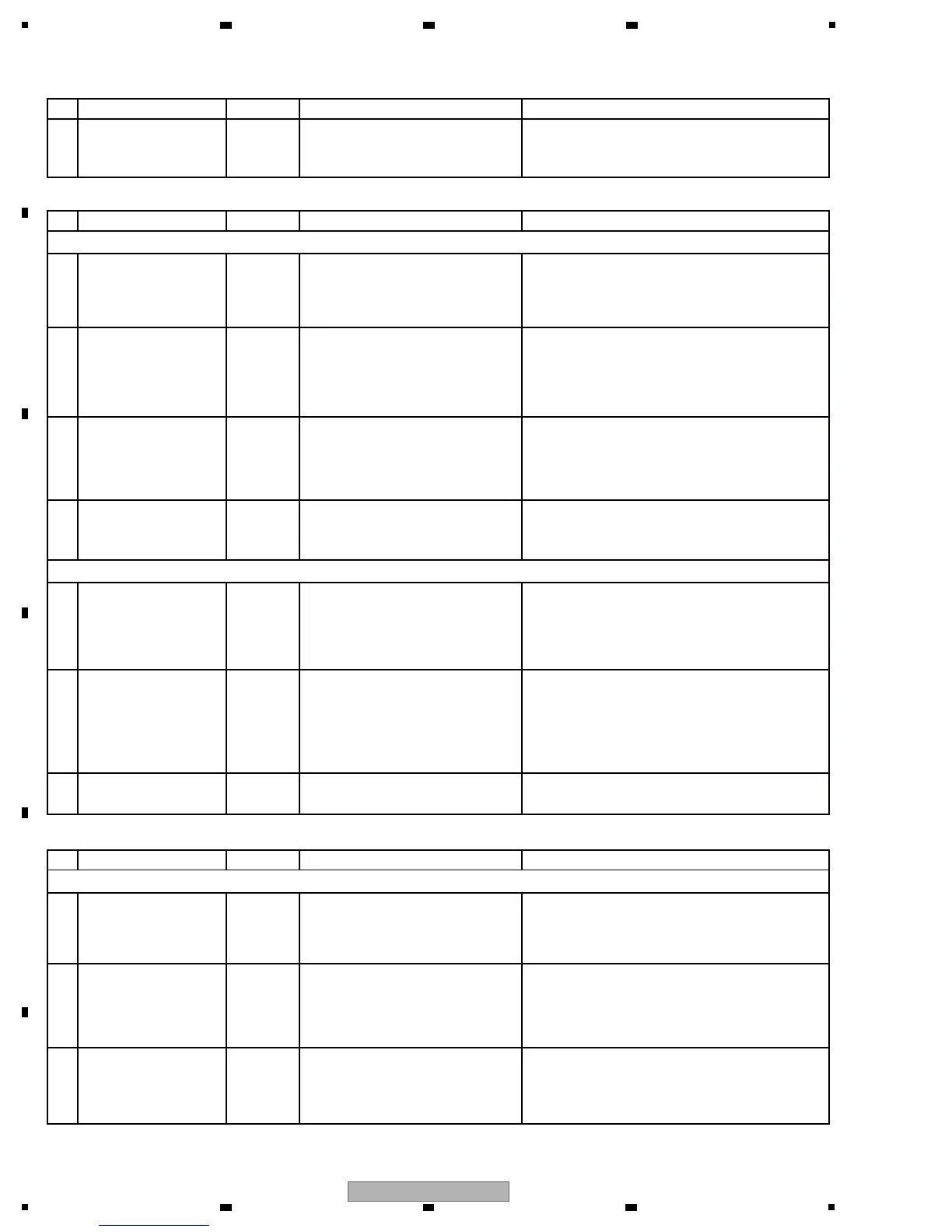
No. Waveform Items for check Causes and measuresPoints to be checked
[5-2] Too low or distorted audio output leve
1
SJACK ASSY
Check that the LED for the
POWER key on the front panel is
lit.
If it is not lit, the cable connecting the SMAIN
and EJTB Assys is not firmly plugged into the
connector of the SMAIN Assy. Reconnect the
cable.
The LED for the EJECT key does not light.
-
No. Waveform Items for check Causes and measuresPoints to be checked
[5-4] LEDs not lit
1
DRIVE UNIT
Check the voltage at the two
electrodes of the LED.
If the voltage in the normal direction is in the
range of 2.2-2.7 V, the LED is defective;
replace it. If the voltage is outside the above
range, the transistor is defective; replace it.
-3
EJTB ASSY
Check the signal at Pin 2 or 5 of
CN350 on the SMAIN Assy.
-2 SMAIN ASSY
Check if the POWER LED on the
front panel is lit.
If it is not lit, the cable connecting the SMAIN
Assy with the EJTB Assy is not securely
connected to the SMAIN Assy. Reconnect the
cable.
The EJECT key does not function.
The USB STOP key does not function.
-
No. Waveform Items for check Causes and measuresPoints to be checked
[5-3] The keys do not function.
1
DRIVE UNIT
If the problem is not resolved, the
SW may be defective or improp-
erly mounted.
Replace the SW.
-4
EJTB ASSY
The SW may be defective or
improperly mounted.
Replace the SW.
-3
FSWB ASSY
Check the input signal at Pin 4 or
6 of CN350 on the SMAIN Assy.
If there is an input signal, check the mounting
status of EXP.IN1 (IC354). If it is properly
mounted, the port connector may be defective;
replace it.
If no signal is input, go to [3].
-2
SMAIN ASSY
Check the input signal at Pin 7 or
8 of CN350 on the SMAIN Assy.
If there is an input signal, check the mounting
status of EXP.IN1 (IC354). If it is properly
mounted, the port connector may be defective;
replace it.
If no signal is input, go to [2].
If there is an no signal, check the mounting
status of AUDIO DSP (IC501). If it is properly
mounted, the port connector may be defective;
replace it.
If signal is input, go to [3].
-
-
1
SMAIN ASSY
Check if the cable connecting the
SMAIN Assy with the EJTB Assy
is securely connected to the
EJTB Assy and if there is
breakage in the cables.
If a connection is loose, firmly connect the
cables.
If there is breakage, replace the Cable.
-3 CABLE
Check if the FFC that connect the
SMAIN and EJTB Assys,EJTB
and FSWB Assys are securely
connected and if there is break-
age in the cables.
If a connection is loose, firmly connect the
cables.
If there is breakage, replace the Cable.
2
CABLE
 Loading...