10 - ATR244 - User manual
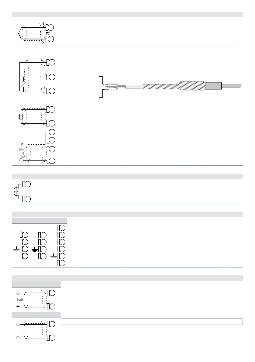
5.1.c Analogue Input AI2 (only ATR244-23x)
AI2
TC
18
17
For thermocouples K, S, R, J, T, E, N, B.
• Comply with polarity
• For possible extensions, use compensated cable and terminals suitable for
the thermocouples used (compensated).
• When shielded cable is used, it should be grounded at one side only.
AI2
PT/NI100
Shield/Schermo
Rosso
Red
Bianco
White
Rosso
18
17
16
For thermoresistances PT100, Ni100.
• For the three-wire connection use wires with the same section.
• For the two-wire connection short-circuit terminals 16 and 18.
• When shielded cable is used, it should be grounded at one side only.
RED/ROSSO
WHITE/BIANCO
AI2
PTC/NTC
16
17
For thermoresistances NTC, PTC, PT500, PT1000 and linear potentiome-
ters.
When shielded cable is used, it should be grounded at one side only to avoid
ground loop currents.
AI2
V
mA
+V
17
15
18
For linear signals in Volt and mA
• Comply with polarity
• When shielded cable is used, it should be grounded at one side only to
avoid ground loop currents.
5.1.d CT input (only ATR244-23x)
C.T.
To enable CT input, modify parameter 287 ct F.
• Input for 50 mA amperometric transformer.
• Sampling time 100 ms.
• Configurable by parameters.
5.1.e Digital inputs
12ABC 12ABC-T 23x
Digital inputs can be enabled by parameters.
Close pin
“DIx”
on pin
“+V”
to enable digital input.
It is possible to put in parallel the digital inputs of different devices joining
togheter the ground pins (15).
13
(PNP)
14
DI1
(PNP)
15
16
+V
(PNP)
14
DI/O1
(PNP)
15
+V
DI3
(PNP)
DI/O2
(PNP)
(PNP)
DI4
(PNP)
21
22
23
24
25
+V
5.1.f Serial inputs (only ATR244-xxxxx-T)
ATR244-12ABC-T
Modbus RS485 communication.
RTU Slave with galvanic insulation.
It is recommended to use the twisted and shielded cable for communications.
RS485
11
12
(B)
ATR244-23x
RS485
(B)
Shield/Schermo
19
9