User manual - ATR244 - 63
13 Alarm Intervention Modes
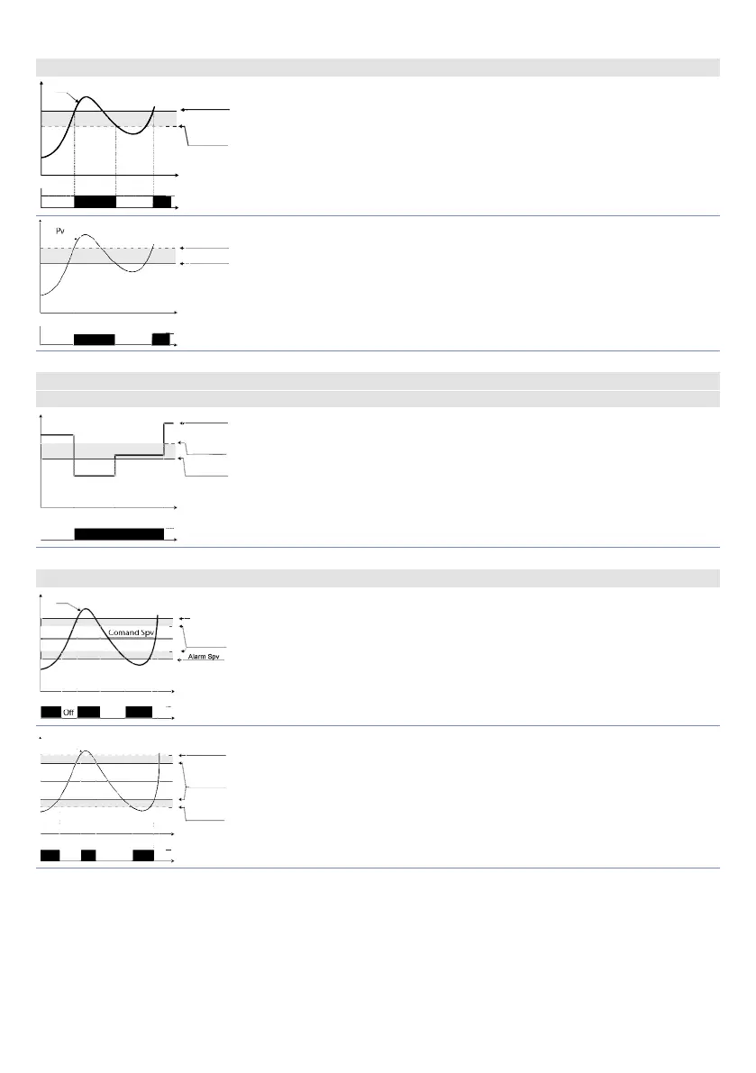
13.a Absolute or threshold alarm active over (par. 123
A L .1 . F.
=
A b . u P. A.
)
Alarm Spv
Pv
O
On On
O
Hysteresis
parameter
> 0
Time
Alarm
output
Absolute alarm.
Hysteresis value greater than “0” (Par. 128
a .1 . H Y > 0).
Alarm Spv
O
On On
O
Hysteresis
parameter
< 0
Time
Alarm
Absolute alarm.
Hysteresis value less than “0” (Par. 128
a .1 . H Y > 0).
13.b Absolute or threshold alarm referred to command setpoint active over (par. 123
A L .1 . F.
=
Ab .c. u.A.
)
O
On
O
Time
Alarm Spv
Hysteresis
parameter
> 0
Alarm
output
Comand Spv
Absolute alarm referred to command setpoint. Hysteresis value
greater than “0” (Par. 128
a .1 . H Y > 0).
13.c Band alarm (par. 123
A L .1 . F.
=
band
)
Pv
Alarm Spv
O O
On On On
Hysteresis
parameter
> 0
Time
Alarm
output
Band alarm hysteresis value greater than “0” (Par. 128 a .1 . H Y > 0).
Pv
Alarm Spv
O O O
On On On
Hysteresis
parameter
< 0
Hysteresis
parameter
< 0
Time
Alarm
Comand Spv
Band alarm hysteresis value less than “0” (Par. 128 a .1 . H Y < 0).