18 - ATR244 - User manual
3
ACTIVE
ACTIVE
SPV
PV
x = COOL
x = COOL
x = COOL
> 0
(HEAT)
COMMAND OUTPUT (HEAT)
ALARM OUTPUT (COOL)
COMMAND OUTPUT (HEAT)
ALARM OUTPUT (COOL)
COMMAND OUTPUT (HEAT)
ALARM OUTPUT (COOL)
SPV
PV
ACTIVE
ACTIVE
Parameter c. c.T.1 has the same meaning of cycle time for heating action c. t. 1.
Parameter c o . f .1 (Cooling Fluid) pre-selects the proportional band multiplier p.b.m.1 and the cooling PID
cycle time
c. c.T.1 according to cooling fl uid type:
c o . f .1
Cooling fl uid type
p.b.m.1 c. c. t.1
Ai r
Air 1.00 10
oi L
Oil 1.25 4
H2o
Water 2.50 2
Once parameter
c o . f .1 has been selected, the parameters p.b.m.1, o.d.b.1 and c. c.T.1 can be however
modifi ed.
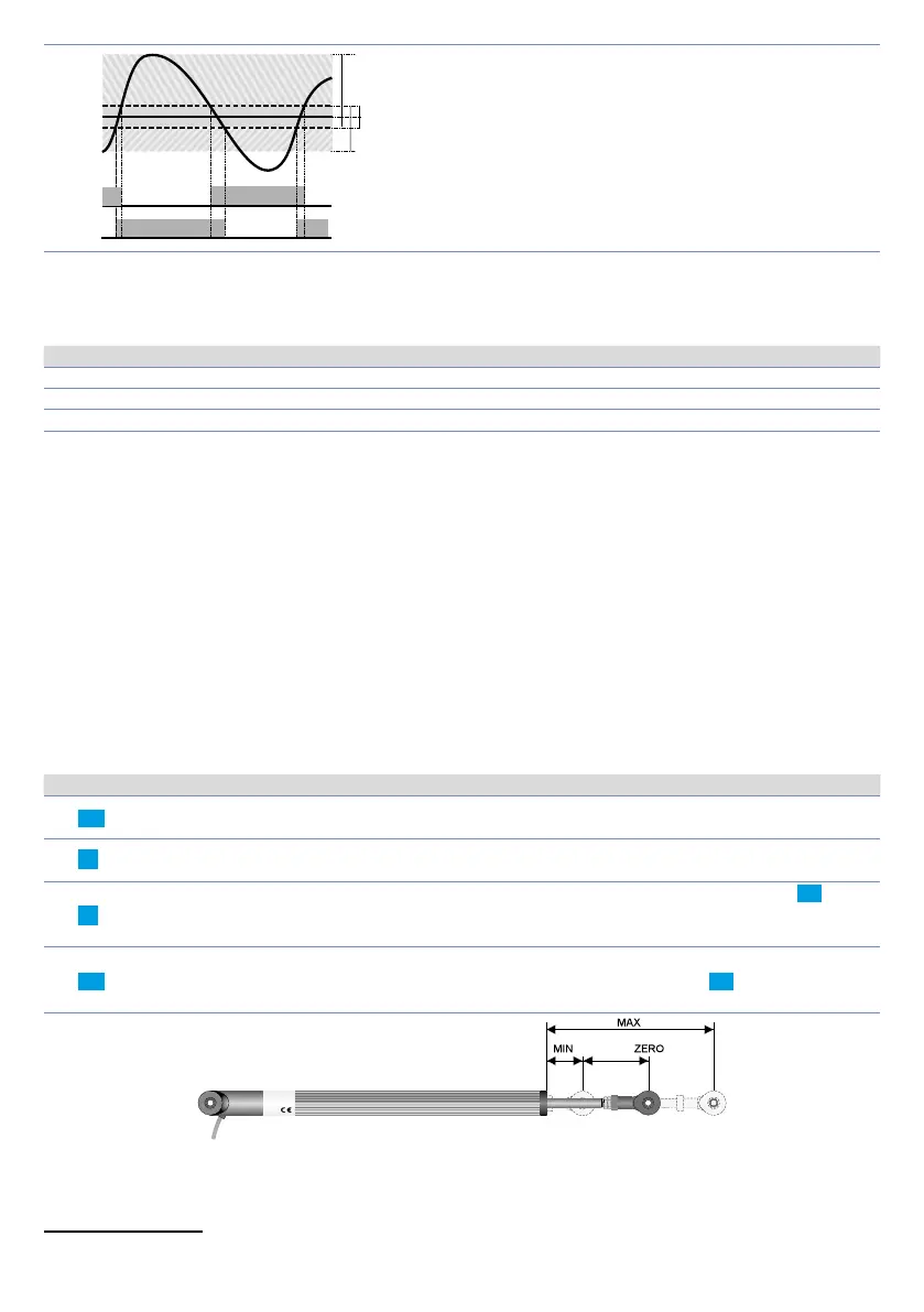
8.10 LATCH ON Function
For use with input pot. and with linear input (0..10 V, 0..40 mV, 0/4..20 mA) t is possible to associate start
value of the scale (par. 4
L.L.i .1 or par. 21 L.L.i .2) to the minimum position of the sensor and value of the
scale end (par. 5
u.L.i.1 or par. 22 u.L.i.2) to the maximum position of the sensor (par. 10 Lt c .1 or par. 27
Lt c.2 confi gured as stndr).
It is also possible to fi x the point in which the controller will display 0 (however
keeping the scale range between
L.L.i .1 / L.L.i .2 and u.L.i. 1 / u.L.i.2) using the
“virtual zero”
option by
selectin
u.0.sto. or u.0.t.on. on par. 10 L t c .1 or 27 Lt c. 2. Selecting u.0.t.on. the virtual zero must be reset at
each switching on; selecting
u.0.sto. the virtual zero will remain fi xed once calibrated. To use the LATCH
ON function, confi gure the par.
L t c .1 or27 Lt c.2.
1
Then refer to the following table for the calibration procedure:
Press Display Do
1
FNC
Exit parameters confi guration. Display 2
visualizes writing
La t c.
Place the sensor on minimum operating
value (corresponding to
L.L.i .1 / L.L.i .2)
2
Store value on minimum.
Display shows
Lo w .
Place sensor on maximum operating value
(corresponding to
u.L.i.1 / u.L.i .2).
3
Store value on max.
Display shows
Hi G h .
To exit standard proceeding press SET.
For
“virtual zero”
setting, place the sensor to
zero point.
4
FNC
Set virtual zero. Display shows
zero .
If
“Virtual zero at start”
is selected, point 4
must be repeated at each starting.
To exit procedure press SET.
1
The tuning procedure starts by exiting the confi guration after changing the parameter.