User manual - ATR244 - 9
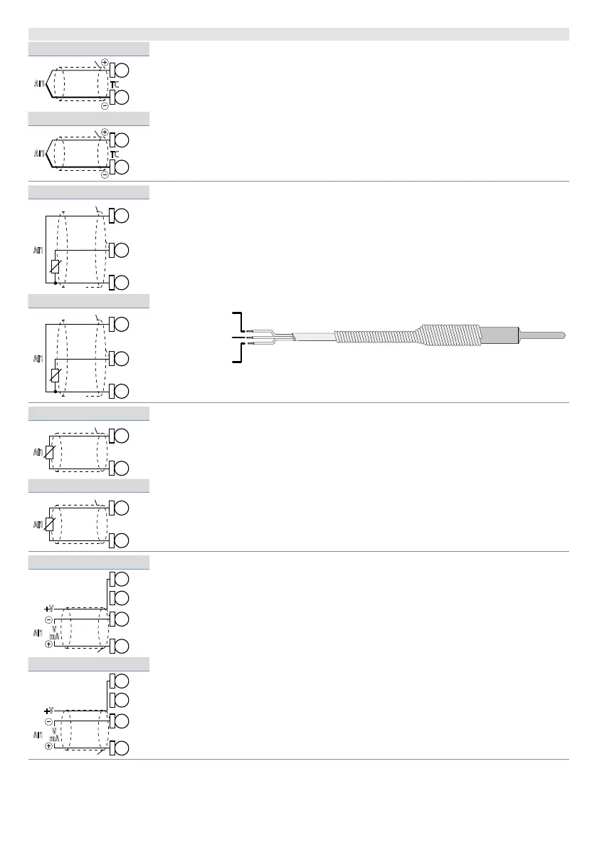
5.1.b Analogue Input AI1
ATR244-12x
For thermocouples K, S, R, J, T, E, N, B.
• Comply with polarity
• For possible extensions, use compensated cable and terminals suitable for
the thermocouples used (compensated).
• When shielded cable is used, it should be grounded at one side only.
AI1
TC
19
18
ATR244-23x
AI1
TC
28
27
ATR244-12x
For thermoresistances PT100, Ni100.
• For the three-wire connection use wires with the same section.
• For the two-wire connection short-circuit terminals 17 and 19 (version
-12x) or 26 and 28.
• When shielded cable is used, it should be grounded at one side only.
RED/ROSSO
WHITE/BIANCO
AI1
PT/NI100
Shield/Schermo
Rosso
Red
Bianco
White
Rosso
19
18
17
ATR244-23x
AI1
PT/NI100
Rosso
Red
Bianco
White
Rosso
28
27
26
ATR244-12x
For thermoresistances NTC, PTC, PT500, PT1000 and linear potentiome-
ters.
When shielded cable is used, it should be grounded at one side only to avoid
ground loop currents.
AI1
PTC/NTC
17
18
ATR244-23x
AI1
PTC/NTC
26
27
ATR244-12x
For linear signals in Volt and mA
• Comply with polarity
• When shielded cable is used, it should be grounded at one side only to
avoid ground loop currents.
AI1
V
mA
+V
18
16
19
ATR244-23x
AI1
V
mA
+V
27
25
28