User manual - ATR244 - 11
5.1.g Digital outputs
12ABC 12ABC-T 23x
SSR output for command or alarm.
Range 12 VDC/25 mA or 24 VDC/15mA selectable by parameter 282
v.out.
(PNP)
12
DO1
(PNP)
(PNP)
14
DI/O1
(PNP)
20
DI/O1
(PNP)
DI/O2
(PNP)
21
24
5.1.h Analogue output AO1
ATR244-12x
Linear output in mA or V (galvanically isolated) configurable as command,
alarm or retransmission of process-setpoint.
The selection mA or Volt for the linear output depends on the parameters
configuration.
AO1
V/mA
9
10
ATR244-23x
AO1
V/mA
10
11
5.1.i Analogue output AO2 (only ATR244-23xx-T)
AO2
V/mA
12
13
Linear output in mA or V (galvanically isolated) configurable as command,
alarm or retransmission of process-setpoint.
The selection mA or Volt for the linear output depends on the parameters
configuration.
5.1.j Relay output Q1
Q1
2A 230V
Resistive
1/8HP
3
4
5
Capacity 2 A / 250 VAC for resistive loads.
See chart below.
5.1.k Relay output Q2 (only ATR244-12x)
Q2
2A 230V
Resistive
1/8HP
7
Capacity 2 A / 250 VAC for resistive loads.
See chart below.
5.1.l Relays output Q2 - Q3 (only ATR244-23xx-T)
Q2
Q3
2A 230V
Resistive
1/8HP
6
7
8
Capacity 2 A / 250 VAC for resistive loads.
See chart below.
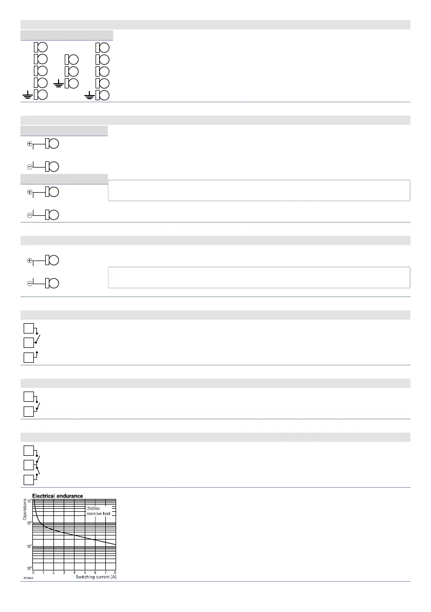
Electrical endurance Q1, Q2 e Q3:
2 A, 250 VAC, resistive loads, 10
5
operations.
20/2 A, 250 VAC, cosφ = 0.3, 10
5
operations.