User manual - ATR244 - 13
7 Dual input mode
Each ATR401 model is provided with two analogue inputs: it is possible to do mathematic operations
between 2 measured process values, correlating obtained result to the command or alarm outputs, or
to give a process value as remote setpoint. It is also possible to use the controller for 2 independent
control loops.
7.1 Selection of process value related to the command
output and to the alarms
When second analogue input is enabled (par.18 sen.2 other than disA b .) it is possible to choose the
process value to be related to command output, to alarms and to retransmission.
Following options are available:
•
A . i n .1 : Value read by input AI1;
•
A.i n .2: Value read by input AI2;
•
mean: Mean between inputs AI1 and AI2;
•
di f f.: Difference between inputs: AI1-AI2;
•
a b . di F: Difference between inputs as absolute value: AI1-AI2;
• Command 1 process must be selected on parameter 36
c . P r.1
• Command 2 process must be selected on parameter 55 c.Pr.2
• The process related to the alarms must be selected on par. 124 a .1 . p r. for the alarm 1, on par. 142
a . 2. p r. for the alarm 2, on par. 160 a .3. p r. for the alarm 3, and on par. 178 a .4. p r. for the alarm 4, on par.
196
a . 5. p r. for the alarm 5 and on par. 214 a . 6 . p r. for the alarm 6.
• The value to be retransmitted must be selected on par. 299
r t m .1 and/or on par. 308 rt m .2.
It is possible to choose what to visualize on display 2 selecting par. 278 ui . d .2.
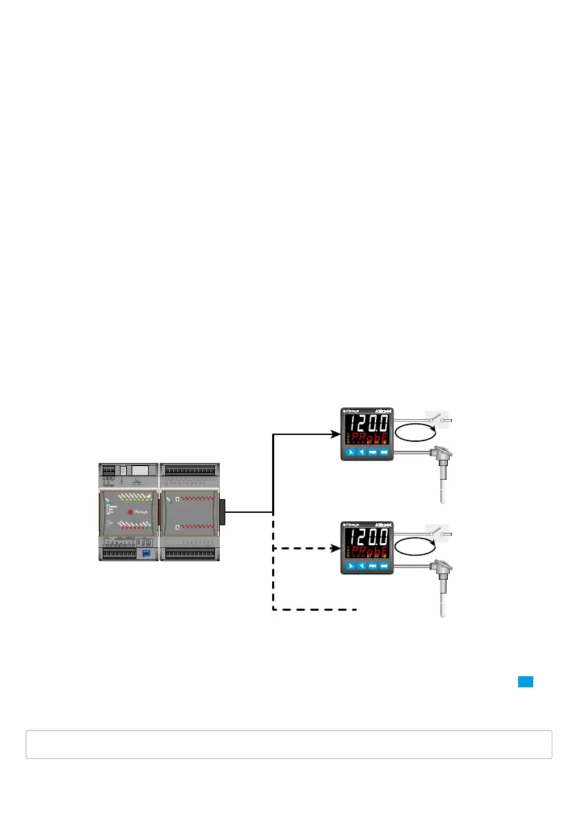
7. 2 Remote setpoint by analogue input
It is possible to enable remote setpoint function setting enab. or en . tst. on par. 56 rem.s.
4...20mA
0...10V
Remote
Setpoint
ATR244
ATR244
PL500 PLE500-6AD
PLC OUTPUT
Probe
AI1
Control loop
OUT
OUT
Probe
AI1
AI2
Remote
Setpoint
AI2
FNC SET
ATR244
C1
C2
MAN
TUN
REM
A2A1 A3
FNC SET
ATR244
C1
C2
MAN
TUN
REM
A2A1 A3
Control loop
DP1
CN3
USB1
CN1
CN2
.4
.5
.6
.7
.3
.2
.1
.0
.4
.5
.6
.7
.3
.2
.1
.0
+0
+1
1 2
3
4
5
6
7 8 9
10
12
QI.0
QI.1
QI.2
QI.3
QI.4
QI.5
QI.6
QI.7
13
14
15 16
17
18 19 20
21 22
23
24
AGND
(0V)
AI0
L+0
AI1
QI.0
QI.1
QI.2
QI.3
QI.4
QI.5
QI.6
QI.7
L+1
AQ.0
AQ.1
AGND
(0V)
In this example the command setpoint is the value read on second analogue input AI2: on par. 55 c. p r. 2
it is selected the input that determines the setpoint.
The Remote Setpoint function is active only selecting
A . i n .1 or A.in . 2 on par. 55 c. p r. 2.
Selecting
en . ts t. on par. 56 rem.s. it is possible to switch from remote to local setpoint pressing SE T for
1 second. The selection is stored even after the subsequent device restarts.
In remote setpoint mode the led REM is ON, it flashes when switching to local setpoint mode.
The decimal point setting parameter for the image input (or remote setpoint) is locked and modifies
automatically when the command input decimal point is changed.