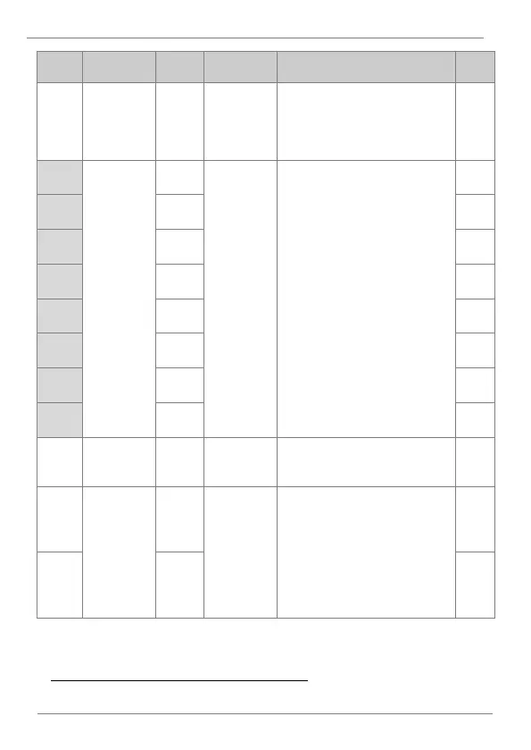
DESCRIPTION OF PROGRAMMING PARAMETERS
Number of
input
parameters
Configure a group of addresses to
read several input parameters at once.
The user must set the number of
parameters and then configure them in
CM.51-58.
Input
communication
addresses 1 to
8
Define the input parameter group for
data transmission, so that addresses
configured in CM.51-58 ca be used to
send several parameters at once in the
same communications frame.
The size of the group is set in CM.50
Swap the most significant byte with the
least significant byte in order to adapt
to the PLC configuration.
Communication
multifunction
input 1 to 7
Multi-function inputs can be controlled
by using the communication address
40902. Configure parameters CM.70-
77 and then set the corresponding bit
in address 40803 for them to operate.
These inputs operate independently
from those set in In.65-71.
] Only parameters corresponding to the value set in CM.50 will be shown (E.g., if
CM.50 = 2, parameters CM.51 and CM.52 will be shown).
 Loading...