DESCRIPTION OF PROGRAMMING PARAMETERS
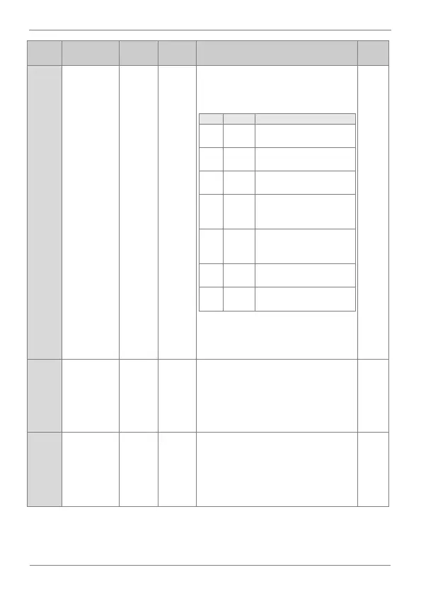
Select
feedback
signal source
Select the source through which the
feedback signal will be introduced to close
the control loop.
Feedback signal by
voltage analog input 1.
Feedback signal by
voltage analog input 2.
Feedback signal by current
analog input 2.
Feedback signal through
Modbus communications
integrated in the drive.
Feedback signal through
any optional
communication boards.
Feedback signal through
the equipment’s PLC.
Feedback signal through
the pulse input.
Note: In case an unavailable option is
selected, the parameter will return to its
previous value.
PID controller
proportional
gain
Set the value of the proportional gain
controller. This value should be increased
whenever a greater control response is
needed.
Note: Increasing too much this value can
cause a greater system instability.
PID controller
integration
time
Set the regulator integration time. In case
greater precision is needed, increase this
value.
Note: Increasing this value may slow down
the system.