Installation and Operation Manual Page 18 of 104
(PVI-3.8/4.6-I-OUTD-US Rev.: 1.1)
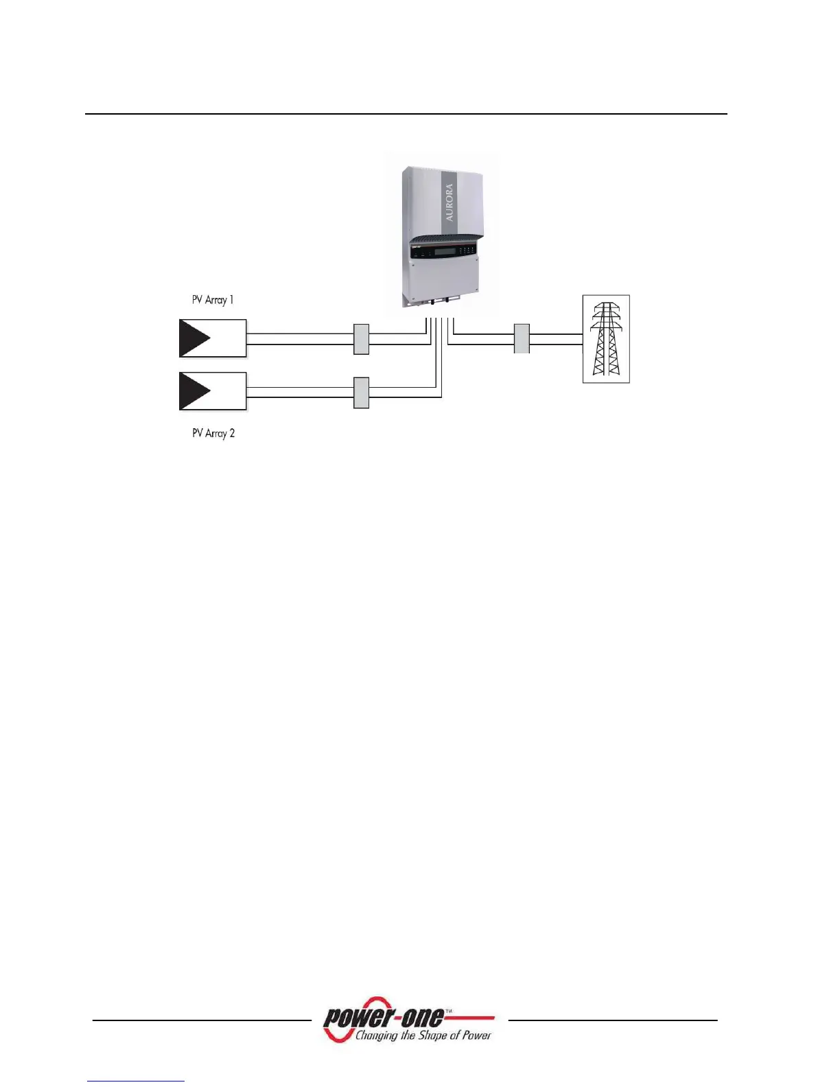
Fig. 3 - Simplified diagram of a photovoltaic system
2.2 Data Transmission and Check
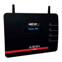
When more than one inverter is used, remote monitoring can be implemented through
a sophisticated communication system based on an RS-485 serial interface. An
optional Aurora Easy-Control system is also available for remote monitoring via the
Internet, analog modem. Moreover, with another option, a radio monitoring system
can be used (PVI-Desktop + PVI-Radiomodule) to obtain a remote display terminal
connected wireless.
2.3 Technical Description of AURORA
Fig. 1 shows the block diagram for AURORA. The main blocks are the input DC-DC
converters (termed 'boosters') and the output inverter. Both the DC-DC converters and
the output inverter operate at a high switching frequency to enable a compact design
and relatively low weight.
These versions of AURORA have a high frequency transformer, i.e. with galvanic
insulation between input and output. The high frequency transformer allows the
primary (DC side) to have galvanic isolation from the secondary (AC side)
maintaining very high performance in terms of energy yield and export. AURORA is
equipped with the necessary protective devices to ensure safe operation in compliance
with applicable regulations as described in the paragraph on protective devices.
DC disconnecting
switch
AC
disconnecting
switch