Installation and Operation Manual Page 87 of 104
(PVI-3.8/4.6-I-OUTD-US Rev.: 1.1)
6 DATA CHECK AND COMMUNICATION
6.1 Connection through RS-485 Serial Port or RJ12 Connectors
6.1.1 RS-485 Serial Port
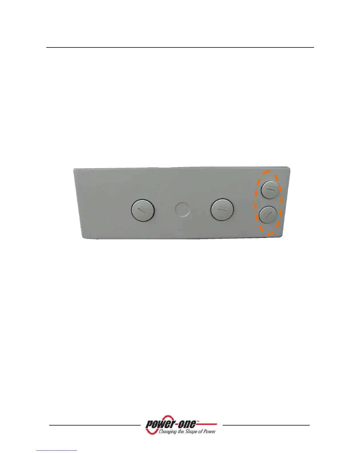
The RS-485 serial port uses a three-wire cable: Two wires are for signals and the third
is for ground connection. The cable is routed through the holes located on the bottom
of the inverter which are blanked with waterproof plugs (see Fig. 26).
The supplied cable gland must be installed in the hole selected for use.
Fig. 26 - Cable routing for RS-485 connection
For ease of installation, the inverter is provided with two holes to differentiate the
input cable route from the output cable route when several units are daisy chained as
described below.
After passing through cable gland, the cables are connected inside the unit to RS-485
terminal blocks which can be accessed by removing the front cover. Refer to
paragraph 3.7 for details on correct front cover removal and reassembly.
The signal wires must be connected to +T/R and –T/R terminals
The ground wire must be connected to the RTN terminal