Installation and Operation Manual Page 47 of 104
(PVI-3.8/4.6-I-OUTD-US Rev.: 1.1)
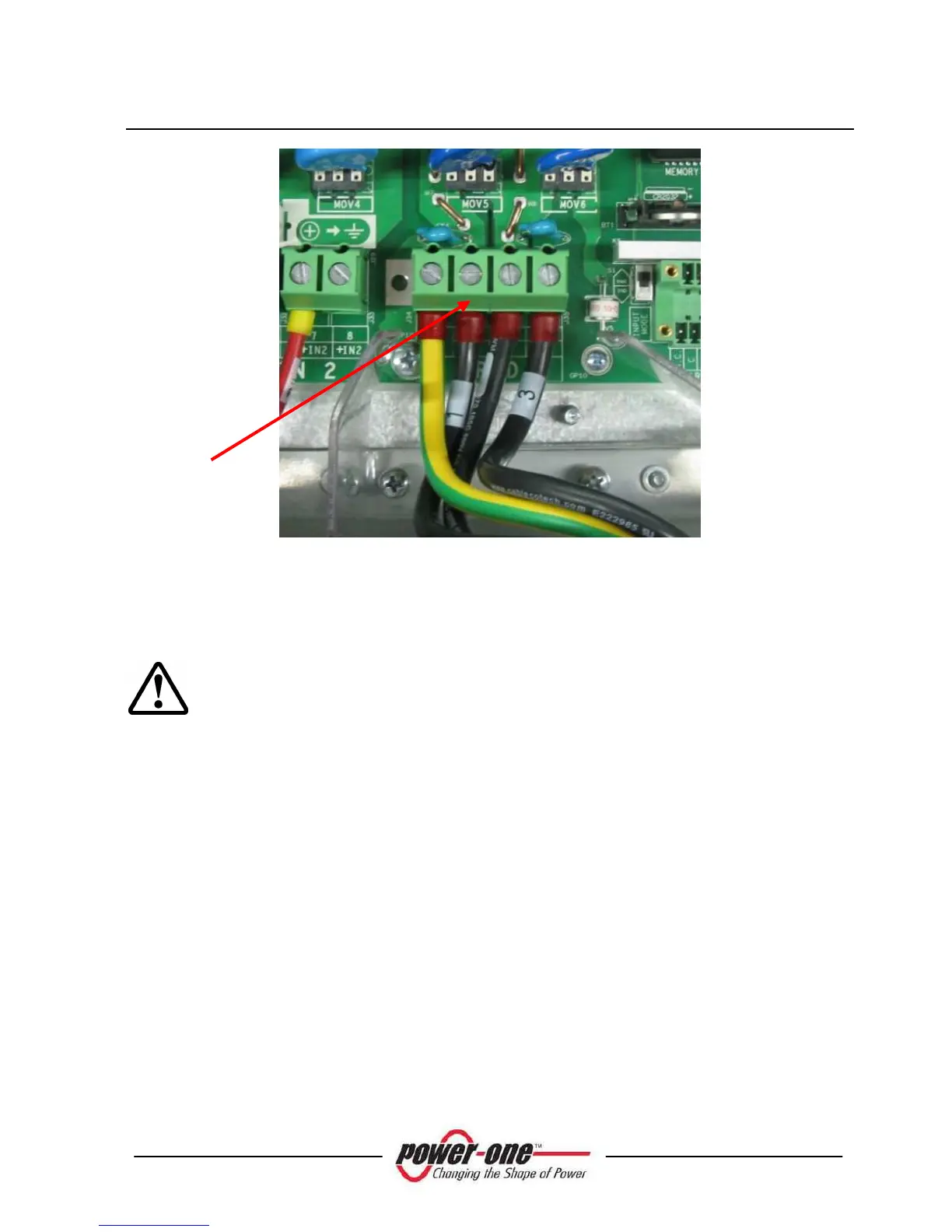
Fig. 18 - Terminal Block for AC connection (-US models)
3.3.8 Connection of RS485 and Alarm contact (optional)
WARNING: Before performing any operation on the Switch Box power
input or on the Inverter, ALWAYS perform the disconnection procedure as
explained in section 3.3.1 or 3.3.2 of this manual.
3.3.8.1 Connection of the RS485 and Alarm contact for -S-US-xx models
Step 1: Remove the Switch Box front panel (remove the 4 screws in pos "B" of
Fig. 11). Remove also the cover of the Aurora inverter (screw pos. "A" of
Fig. 11) in order to gain access to the terminal block board.
Step 2: Lay down the cables between the Aurora inverter and the outside passing
trough the provided holes and cable plastic conduit on the Switch Box.
Step 3: Connect the communication and the alarm cables to the communication and
alarm terminal block on the right side of the inverter. Follow the marking on the
terminal block for appropriate connection.
A