Installation and Operation Manual Page 22 of 104
(PVI-3.8/4.6-I-OUTD-US Rev.: 1.1)
3.1.1 Inspecting package contents
Description Quantity (No.)
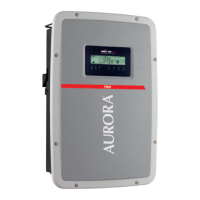
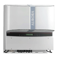
Aurora Inverter 1
Bag containing:
Nr.4 6.3x70 screws, nr.4 SX10 blocks, 2 cables
AWG10, Torx20 wrench, nr.1 6x10 screw, nr.5 d.18
washer, 2 counterparts for signal connectors (3
poles), 2 counterparts for signal connectors (8 poles)
Nr.1 wall mounting bracket
1
Installation and Operator's Manual 1
Certificate of warranty 1
CD-ROM with communication software 1
3.2 Selecting the installation location
Installation location should be selected based on the following considerations:
• Height from ground level should be such as to ensure that the display and status
LEDs are easy to read.
• Select a well-ventilated location sheltered from direct sun radiation. Choose a
location that allows unobstructed airflow around the inverter.
• Allow sufficient room around the inverter to enable easy installation and removal
from the mounting surface.
• A door is provided on the front of the inverter to allow for hardware maintenance.
The following figure shows the recommended minimum clearances around the
inverter: