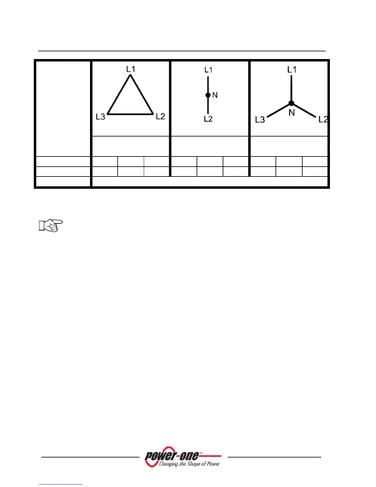
GRID STANDARD
208V~
3PH - ∆
240V~
SPLIT- PHASE
277V~
3PH - Υ
TERMINAL
1 2 3 1 2 3 1 2 3
WIRE
L1 * L2 * - L1 L2 N N L1 * -
AWG #
4 - 8
Table CN-01 – AC Grid Connections
(*) IMPORTANT: If several Aurora inverters are installed in a tree-phase
AC GRID, it is recommended to distribute the inverters between the phases
in order to reduce the power unbalances between the phases. Always refer to
the local standards.
3.3.7.2 Connection to the AC GRID for -US-xx models
Step 1: Remove the Inverter front panel (remove the 4 screws in pos “A” of
Fig. 11).
Step 2: Lay down the cable between the Aurora inverter and the AC disconnect
switch.
Step 3: Pass the AC cable inside Aurora through one of the cable glands present in the
lower side of the Inverter
Step 4: Connect the 3 AC wires to the relative terminal block present inside the
Inverter (Fig. 18). The AC wire connections should be done based on the type of AC
Grid by following Table CN-01 –"AC Grid Connection ". The ground cable shall be
connected to the terminal block indicated by the pointer of pos. "A" of Fig. 18.