Installation and Operation Manual Page 50 of 104
(PVI-3.8/4.6-I-OUTD-US Rev.: 1.1)
Aurora units grounding mode is identified by PN; -xx-PG indentify a unit with
Positive Grounding while -xx-NG a unit with Negative Grounding.
NOTE: Choose the PN in order to fulfil plant requirements.
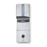
Fuse holder is place on the bottom of the inverter (inside the Switch Box for -S-US
models) as shown on Fig. 14 Part “I”. Unscrew the fuse holder in order to change the
fuse if necessary. Replace only using appropriate fuses:
Littelfuse KLKD-1
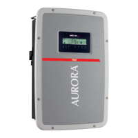
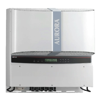
3.4 Disconnecting the AURORA Inverter from the DC Switch Box (only -S-
US-xx models).
Use the procedure in paragraph 3.4.1 anytime that it is necessary to electrically
disconnect the Aurora inverter from the DC Switch Box.
3.4.1 ELECTRICAL DISCONNECTION OF THE INVERTER FROM
THE SWITCH BOX PROCEDURE
WARNING: The Aurora inverter operates at high voltages that can be
extremely dangerous! CARFULLY FOLLOW EACH STEP OF THIS
PROCEDURE in order to avoid injury to personnel and/or equipment
damage.
STEP 1: Disconnect the inverter from the AC Grid using the AC disconnect switch
shown as " Part "D" in Fig. 9 " Connection Diagram".
STEP 2: Disconnect the High Voltage DC power line coming from the photovoltaic
arrays using the appropriate switch (switch "C" of the Switch Box shown in Fig. 12).
Turn the switch to the OFF position as shown on the silk print shown in Fig. 12.
STEP 3: Wait about 5 minutes to allow the internal capacitors to discharge (verify that
the LEDs on the front panel are OFF). This step completes the electrical
disconnection of the inverter from the DC Switch Box.