Installation and Operation Manual Page 43 of 104
(PVI-3.8/4.6-I-OUTD-US Rev.: 1.1)
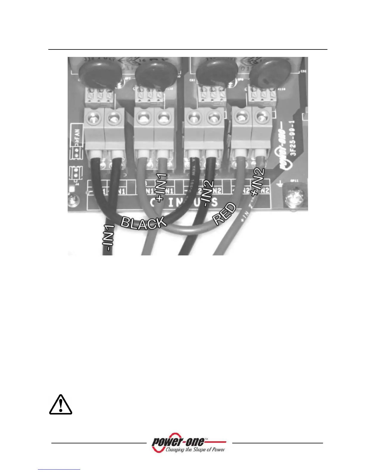
Fig. 16 - Parallel Connection
The switch “S1” indicated in Fig. 15 should be placed to position “PAR” (default
position) in order to configure the inverter in parallel mode (default set-up).
After switching the Aurora inverter to parallel mode configuration, the front panel
should be reinstalled (apply 13.2 in-lbs of torque to each of the 4 screws). After the
front panel is secured, it is possible to begin the START-UP procedure. (see
section 4).
3.3.7 Connection to the AC GRID
WARNING: Before performing any operation on the Switch Box power
input or on the Inverter, ALWAYS perform the disconnection procedure as
explained in section 3.3.1 or 3.3.2 of this manual.