Installation and Operation Manual Page 39 of 104
(PVI-3.8/4.6-I-OUTD-US Rev.: 1.1)
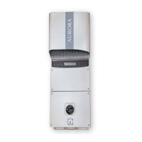
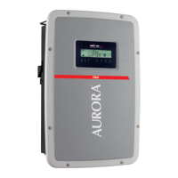
3.3.5 AURORA Inverter Typical Electrical Installations.
WARNING: THE INPUT CURRENT shall not exceed 14 Adc for PVI-4.6-
I-OUTD, 12.5A for PVI-3.8-I-OUTD for each input channel.
3.3.5.1 Installation of -S-US-xx models
WARNING: For -S-US-xx models, before performing any operation on the
Switch Box power input, ALWAYS perform the disconnection procedure
explained in section 3.3.1 of this manual.
Step 1: Disconnect from the AC Grid by turning Off the"AC Bipolar Switch" – Part
"D" in Fig. 9.
Step 2: Remove the Switch Box cover and the Inverter cover as described in section
3.3.3 and connect the DC cable to the terminal block at pos "A" in Fig. 14 carefully
check the correct polarity of the DC cable.
Step 3: Connect the AC cable by following the instructions in section 3.3.7. Refer to
Table CN-01 "AC Grid Connection"
Step 4 (optional): Open the inverter cover as described in section 3.3.3 and connect
the signal cable. Pass the cables inside the Switch Box through the input knockouts
(see pos "D" Fig. 12), put the signal cables inside the plastic conduit (see pos "H" Fig.
14), and then inside the inverter through the cable gland placed in the upper side of the
Switch Box; finally screw the cables to the connectors counterparts present in the
mounting kit and connect it to the inverter.
Step 5: Remove the cover from the photovoltaic panel or wait for the sun to irradiate
the panel
WARNING: Verify that the DC voltage in the Switch Box input (terminal
block pos. "A" Fig. 14) has the correct polarity and is within the operational
range.