Installation and Operation Manual Page 35 of 104
(PVI-3.8/4.6-I-OUTD-US Rev.: 1.1)
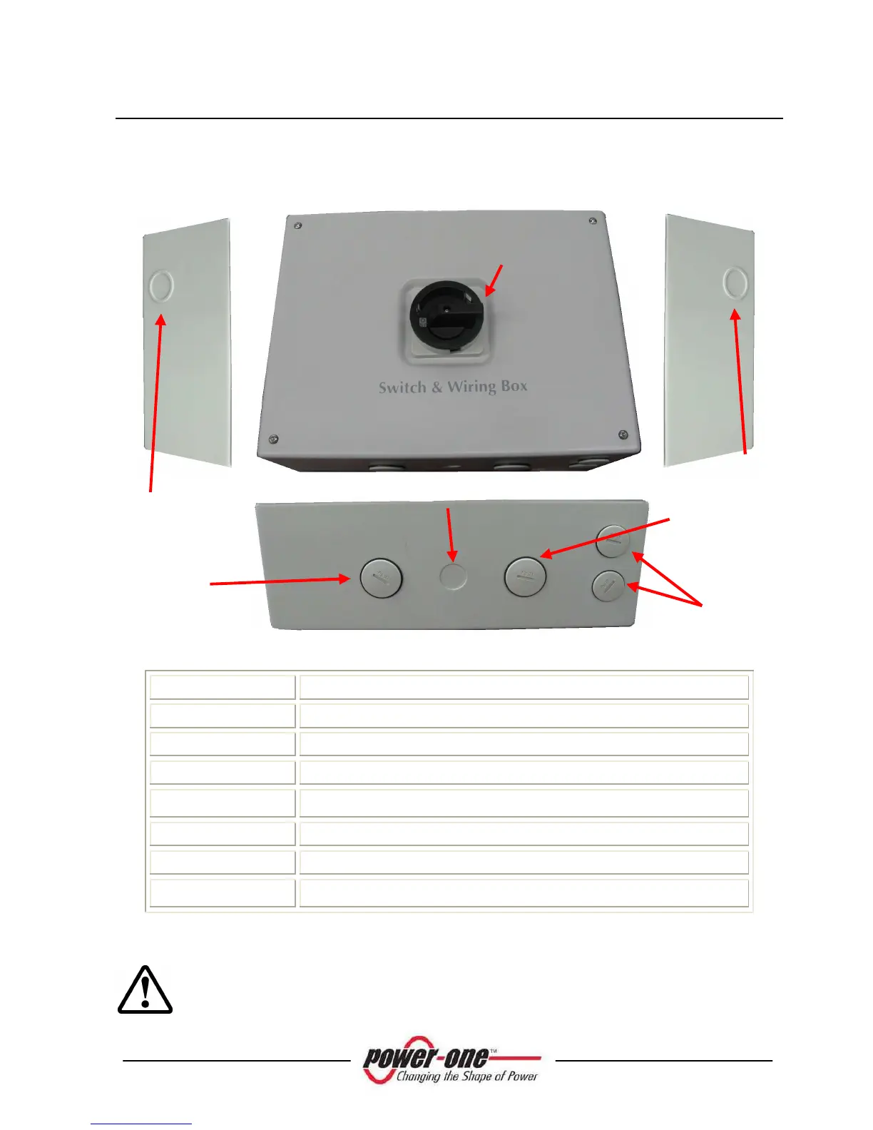
3.3.4 Aurora Switch Box Description
Fig. 12 - DC Switch Box Layout
Pos. Fig. 11 Description
A DC Power cable knockouts – SIZE: 1”, ¾”
B AC Power cable knockouts – SIZE: 1”, ¾”
C DC Switch
D
Signal cable entries – SIZE:
½”
E AC Power cable hole – SIZE: ¾”
F DC Power cable hole – SIZE: ¾”
G
Ground cable knockout – SIZE:
½”
WARNING: The Switch Box disconnects the DC current from the
photovoltaic panels when the switch is in “OFF” position (see the electrical
schematics in Fig. 12 and DOES NOT disconnect the AC line going to the
A