Installation and Operation Manual Page 37 of 104
(PVI-3.8/4.6-I-OUTD-US Rev.: 1.1)
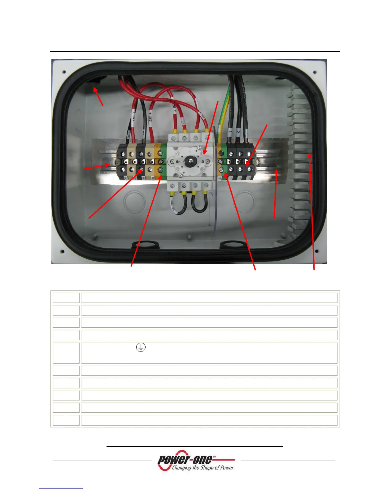
Fig. 14 - Switch Box, Internal View
POS Details
A
DC terminal input
B
DIN bars for accessories
C
DC switch
D
Main Ground - Max Wire Size = AWG# 4 (Refer to local code for
minimum wire size)
E
Ground
F
AC terminal output
G
Cable Knockouts : SIZE 1”, ¾”
H
Plastic conduit for signal cables
I
Fuse Holder
Table SBD – Switch Box Internal Parts Summary.
A