Installation and Operation Manual Page 90 of 104
(PVI-3.8/4.6-I-OUTD-US Rev.: 1.1)
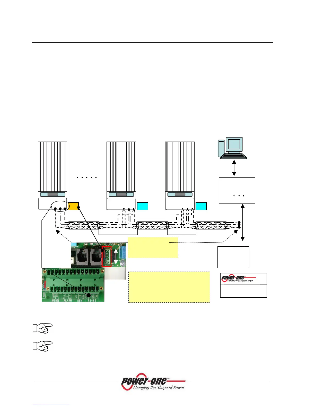
In order to ensure optimum communication on the RS485 line, Power-One
recommends connecting the PVI-RS232485 adapter to a location between the first unit
of the daisy chain and the computer. See Fig. 28 for further details.
Other equivalent devices available on the market can also be used but Power-One does
not assure correct connection operation since these devices have never been
specifically tested.
Please note that these other equivalent commercial devices could require external
termination impedance, which is not necessary for Aurora PVI-232485.
The following diagram shows how to connect multiple units into a daisy chain
configuration.
Fig. 28 – Daisy Chain Connection
NOTE
:
When using an RS-485 link there can be up to 64 inverters connected on
the same link. Choose any address between 2 and 64.
NOTE
:
When using an RS-485 link, in case one or more inverters are added
later to the system, please remember to switch the inverter switch of the
former last inverter of the system back to the OFF position.
RTN
+T/R -T/R
RTN
+T/R -T/R
RTN
+T/R -T/R
1
Recommended RS-485 cable type:
LiYCY, 2x2x0.5 mm (no.2 twisted
pairs) + shield
RS-485 cable (1 pair + 1 conductor)
+ shield