Chapter 5 Function parameter
96
carrier frequency, the equipped leakage protective device may cause malfunction or
overcurrent.
When running at the low carrier frequency, the above-mentioned phenomenon are
opposite.
There are different responds to carrier frequency for the different motors. The best
carrier frequency can be obtained based on the Actual situation adjustment. However, with
the increase of motor capacity, the smaller carrier frequency should be selected. This
company reserves the right to limit the maximum carrier frequency.
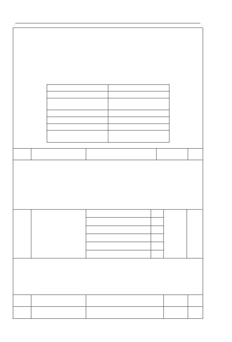
The adjustment of carrier frequency will have impacts on the following performances:
External radiation and
interference
Note: the larger the carrier frequency, the higher the whole unit temperature
If analog input, pulse input (DI5) or multi-stage command in PI9000 is selected as
frequency source, the respective 100.0% is calibrated relative to the parameter.
When PI9000 maximum output frequency reaches up to 3200Hz, in order to take into
account the two indexes of frequency command resolution and frequency input range, the
number of decimal places for frequency command can be selected by F0.02 .
When F0.02 selects 1, the frequency resolution is 0.1Hz, at this time F0.19 can be set in
the range from 50.0Hz to 3200.0Hz; When F0.02 selects 2, the frequency resolution is
0.01Hz, at this time F0.19 can be set in the range from 50.00Hz to 320.00Hz.
Upper limit frequency
source
Panel potentiometer setting
Setting upper limit frequency. The upper limit frequency can be set from either digital
setting (F0.21) or analog input channels. If the upper limit frequency is set from analog input,
the set 100% of analog input is relative to F0.21.
To avoid the "Runaway", the setting of upper limit frequency is required, when the
inverter reaches up to the set upper limit frequency value, the inverter will remain operation
at the upper limit frequency, no further increase.
F0.23 (lower limit frequency) to
F0.19 (maximum frequency)
Upper limit frequency
offset
0.00Hz to F0.19 (maximum
frequency)
 Loading...

