Chapter 5 Function parameter
123
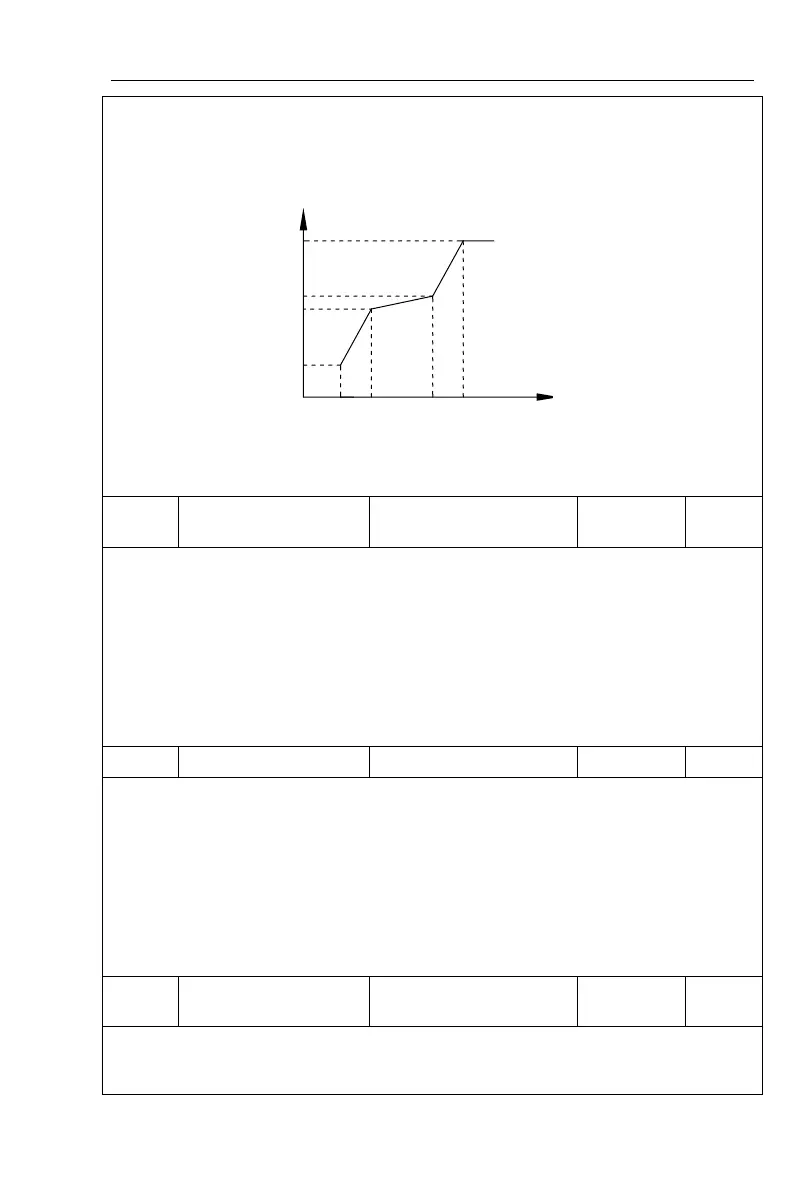
meet: V1 <V2 <V3, F1 <F2 <F3. The setting of multi-point V/F curve is as shown in below
figure.
In the sate of low frequency, if the voltage is set to a higher value, which may cause
motor overheating even burned, the inverter may appear overcurrent stall or overcurrent
protection.
V/F slip compensation
gain
This parameter is valid only for asynchronous motors.
V/F slip compensation can compensate for the speed deviation of asynchronous motor
when the load increases, so as to keep stable speed when the load changes.
If V/F slip compensation gain is set to 100.0%, it means that the compensated deviation
is equal to the rated motor slip under the rated motor load mode, while the rated motor slip
can be calculated through b0 group of motor rated frequency and rated speed.
When adjusting V/F slip compensation gain, generally it is based on the principle that
the motor speed is same as the target speed. When the motor speed is different from target
value, it is necessary to appropriately fine-tune the gain.
In the process of the inverter's deceleration, the over-excitation control can suppress the
rise of bus voltage to avoid overvoltage fault. The greater overexcitation gain, the stronger
the inhibitory effect.
For the occasions that the inverter's deceleration easily cause over pressure alarm , the
overexcitation gain needs to be improved. But if overexcitation gain is too large, which easily
lead to the increase of output current, you need to weigh in practical applications.
For the small inertia occasions that the inverter's deceleration will not cause voltage rise,
it is recommended to set overexcitation gain as 0; the set value is also suitable for the
occasions with braking resistor.
V/F oscillation
suppression gain
The method of selecting gain is take the value as smaller as possible with the premise
that effectively suppressing oscillation, in order to avoid the adverse affect caused by V/F
running. Please select 0 as the gain when the motor has not oscillation phenomenon. Only
V1-V3: Voltage percentage of stage 1-3 to multi-speed V/F F1-F3: Frequency percentage of stage 1-3 to multi-speed V/F
Vb : Rated motor voltage Fb: Rated motor operating frequency
Schematic diagram of multi-point V/F curve setting
 Loading...

