ProgrammerManual PTX‐S828
Chapter5IPDSProgrammingInformation 167 260071‐001A
Decimal Hex Value Description
16-17 10-n Reserved
Notes:
1. For bytes 5 through 6 (units per base value), 14400/10 in. is supported precisely. Multiples of 14400/10 in.
are also supported. If byte 4 specifies units in centimeters and byte B specifies 20 (center-and-trim) or 30
(position-and-trim), then bytes 5 through 6 must be equivalent to a supported value such as X'1626' or
X'2C4C'.
2. See “Area Mapping Control Options”.
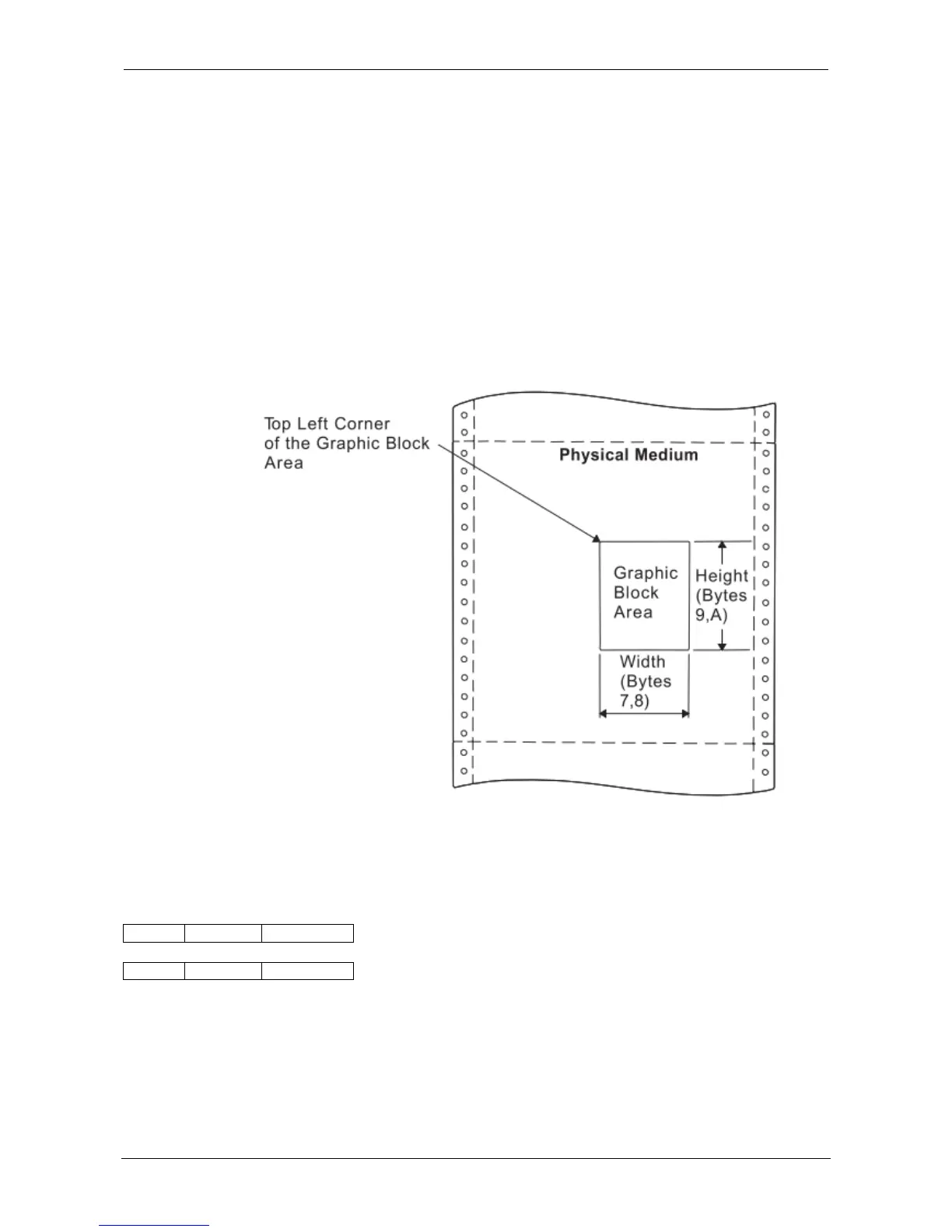
3. The printer ignores the X and Y offset fields unless byte B equals X'30'. These values are the offset of the
top left corner of the graphic window relative to the top left corner of the graphic block area.
Figure 21 shows the Graphic Output Control parameters specifying the size of the graphic block area.
Figure 21. Graphic Output Control and the Graphic Block Area
Graphic Data Descriptor (GDD)
GAP GOC GDD
Length ID DATA
The Graphic Data Descriptor is the last structured field in the DATA portion of the Write Graphics Control
command. This field specifies the parameters for the graphic window in the graphic medium presentation
space (GPS) and sets the drawing default conditions. The graphic window limits define the range of
drawing order coordinate values that map to the graphic block area.
Without causing an error, the drawing orders can specify GPS coordinates in the X'8000' to X'7FFF' range.
The specified GDD graphic window limits select the part of the drawing order’s picture to consider for
mapping to the output area.