Do you have a question about the Procom DVS-21 and is the answer not in the manual?
Details on installation requirements and user account access.
Information on system and monitor file extensions.
Description of available menu items and their functions.
Overview of toolbar icons for online functions and system configuration.
Configuration for language, default values, color, and templates.
Configuration of the serial interface for system communication.
Tool for checking system functions and monitoring telegram traffic.
Module for reading and writing system programs.
Procedure for updating the system CPU firmware.
Module for updating the system time.
Module for simulating telegrams and testing modules.
Direct access to system program data for editing.
External program for evaluating recorded telegram traffic.
Dialog for investigating differences between two configuration files.
Recording, playback, and testing of the DSS1 module.
Preview and printing of system documentation.
Dialog for listing possible logic errors in the configuration.
Internal table of previously archived version dependencies.
Configuration of general system data and identification.
Overview and configuration of system call stations and devices.
Overview and configuration of modules within the system rack.
Overview and management of system programs.
System supply and CPU monitoring module with fault message.
Processor unit with display and control elements.
Processor module for special tasks and LAN connectivity.
Carrier module for up to 4 module attachments.
Audio Frequency interface module for four ProCom stations.
Interface module for up to four ProCom stations with two-wire technology.
Audio Frequency interface module for four stations with V- and C- point.
Connection module for two exchanges, analog, 4-fold.
Digital memory for storing audio recordings and detection of frequencies.
Interface module with floating in- and outputs.
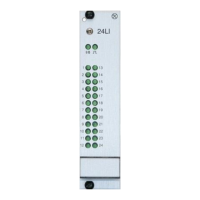
Line module for driving 24 lines with surge protection.
Module for data acquisition and processing of 4 measuring microphones.
Interface module with serial RS232 for specific tasks.
100W digital amplifier for public address and standby operation.
Module supporting various modes in analog telephony.
Tone generator for Impedance Measurement Module 4LSL.
Measurement module for loudspeaker line monitoring.
Module designed to connect UZ-ELA modules for loudspeaker systems.
Passive module for manual attenuation of 4 loudspeaker lines.
Introduction to call stations and other devices like measuring microphones.
Details on various configurations of ProCom call stations.
Connecting and configuring analog call stations from other manufacturers.
Connection and setting of PC call stations.
Registering a measuring mic for fuse monitoring activation.
Controlling spatially separated analog amplifiers.
Explanation of parent configuration boxes for AF-programs.
Program to control DSS1 module for recorded sounds playback.
Display and acknowledgment of fault reports on ProCom stations.
Program to establish local intercom connections between call stations.
Program for unilaterally-controlled connections via intercom.
Program for simultaneous connections with multiple call stations.
Program for switching radio stations with frequency band differentiation.
Program for switching on monitoring for radio or PA loudspeakers.
Program for local, simultaneous speech connections to multiple stations.
Program for LB connections and LB repeater via Module USE2.
Program for transmission of LB telegrams in temporary systems.
Program for local control of an amplifier.
Program for remote amplifier control and forwarding.
Universal program for switching AF and lines.
Program for switchboard connections via RS485.
Program for intercom in split systems.
Linking local groups running IC Group program in split systems.
Simultaneous, single-sided speech connection to multiple stations.
Transmission of Remote-Intercom connections in temporary systems.
Intercom connection between DVS-21 and analog third party system.
Programming logical connections with combinable time responses.
Configurable inputs for Flag Input/Output program logic.
Program for triggering actions at fixed time intervals.
Process control for internal impedance measurement of the V100 amplifier.
Changing module level via soft function keys on a station.
Selective attenuation and automatic volume control.
Program for transmission of LB telegrams via cascaded systems.
Program for transferring telephone numbers to the USE2 module.
Switching of lines and basic logic operators between Line and Flag.
Synchronizing internal clock to an external 24-hour time cycle.
Program to counteract problems with line block transmission.
Program to counteract problems with special line transmission.
Universal input mask for configuring 32-byte datasets.
System supply and CPU monitoring module with fault message.
Processor unit with display and control elements.
Processor module for special tasks and LAN connectivity.
Carrier module for up to 4 module attachments.
Audio Frequency interface module for four ProCom stations.
Interface module for up to four ProCom stations with two-wire technology.
Audio Frequency interface module for four stations with V- and C- point.
Connection module for two exchanges, analog, 4-fold.
Interface module with floating in- and outputs.
Line module for driving 24 lines with surge protection.
Module for data acquisition and processing of 4 measuring microphones.
Interface module with serial RS232 for specific tasks.
100W digital amplifier for public address and standby operation.
Module supporting various modes in analog telephony.
Tone generator for Impedance Measurement Module 4LSL.
Measurement module for loudspeaker line monitoring.
Module designed to connect UZ-ELA modules for loudspeaker systems.
Passive module for manual attenuation of 4 loudspeaker lines.
Diagrams of station keypad layouts for different models.
| Brand | Procom |
|---|---|
| Model | DVS-21 |
| Category | Conference System |
| Language | English |