User Guide
DVS-21
02/2018 • V.1.0 • L. Wolle
© 2017 ProCom
®
Professional Communication & Service GmbH • Technical changes reserved.
Special input (Selection box)
Polling of the state of an outgoing line on a module
Module fault report polling
Polling of a module regarding a fault report
Helpful for modules with active self-monitoring such as V100 and modules with
front-mounted fuses, as well as 4NSA with stations or 4FTR with long-distance
lines. In the case of modules without self-monitoring such as 24LI only the lack
of the module is noted.
Polling whether a specific amplifier is currently performing the Impedance
measurement of its loudspeaker line. Only functions if the Impedance
measurement program has been used.
Not to be confused with Impedance measurement by the 4LSL module!
At least the Impedance flag and the amplifier number must be specified.
Polling whether the port of a module has switched to active AF
Polling whether the port of a module has switched to incoming AF
Polling whether the port of a module has switched to outgoing AF
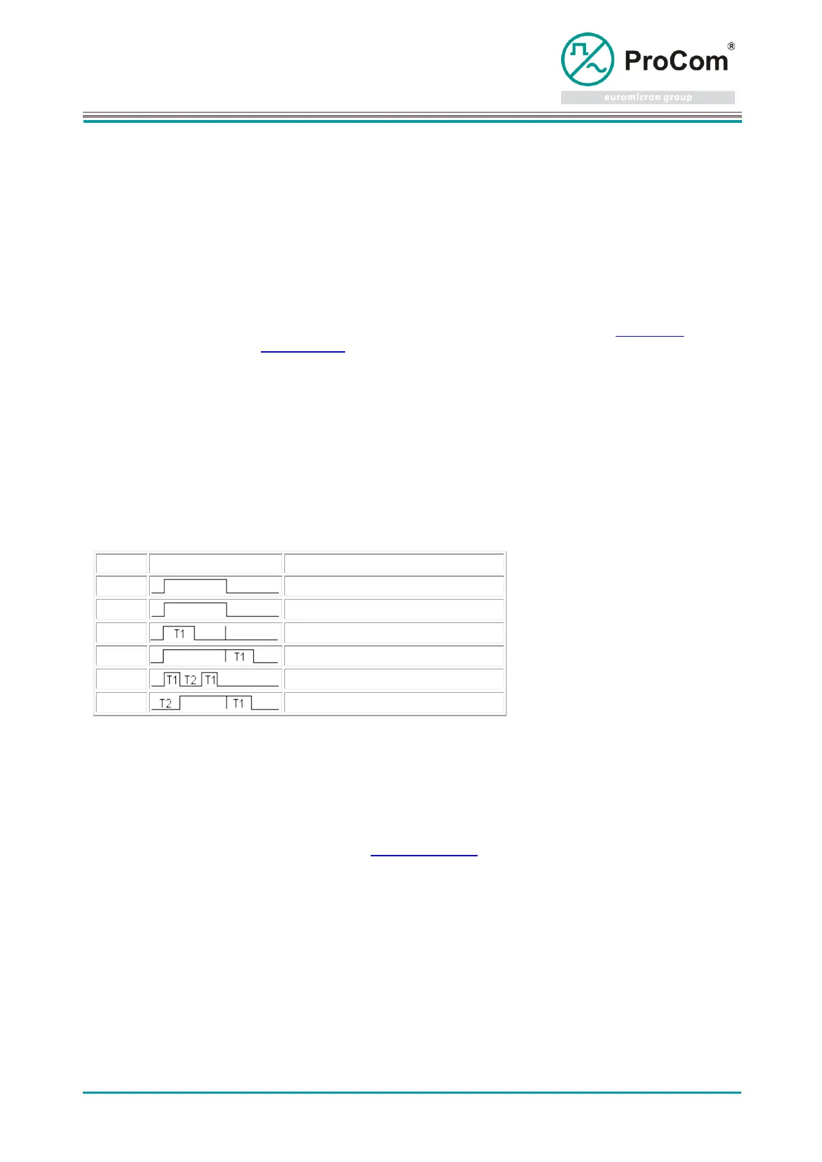
Timer
For the programming of temporal behavior,Timer 1 - Timer 4 can be stopped at an immediate point. . The
intervals of the timer are determined by Times T1 and T2. The maximum time 32000 seconds (>8 hours).
No timer, output follows the input
Follow-up time, time runs from end
Combination of delay and follow-up
10.2 Flag Input/Output 2
Programming logical connections with combinable time responses
Note! Expanded information via AF channels (Audio channel) in a Flag are not transferred!
The inputs are configurable in relation to the Flag Input/Output program. Each input has a switch to select
the logic. The inputs of the 3rd gate can can be decoupled as desired, in order to use the 1st and 2nd
gate separately or in combination.
Procedure:
An output of the program becomes active if this is permitted by its input and timer conditions!
Only inputs in which a Flag or a Line is entered, are taken into consideration. Inputs with a 0 entry are
ignored.
At least one Flag (OR) or at least two Flag (AND) must be active in order for the output to be active as
well. The Flag 255 (Always ON)is available for continuous activation.