User Guide
DVS-21
02/2018 • V.1.0 • L. Wolle
© 2017 ProCom
®
Professional Communication & Service GmbH • Technical changes reserved.
Activates use of the Module Address
decoder for expansion of the
addressable module addresses.
Introduction of the backplane cancels
the use of the Address decoder!
Sets the behavior of clock-LEDs of all
programmed modules.
The initialization of the module at boot
time is visualized by rapid flashing
(fast blinking). LEDs of non-
programmed modules are flashing,
regardless of this setting!
Selection
LEDs are off after
init. phase, short
flashing in case of
test frames
LED's are on after
init. phase
LED's are off after
init. phase
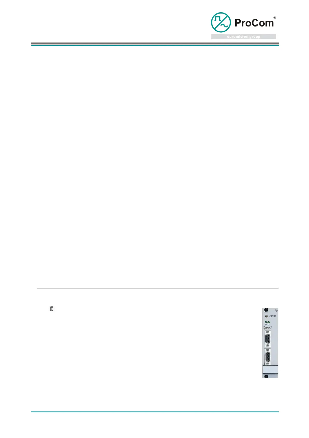
As from Hardware Version 6.01, the
CPU is equipped with an external
clock synchronization input. This
enables synchronization with an
external transmission technology
clock. The default settings can be
used for the most common
applications. If required, adaptations
can be made for line length, signal
type and impedance.
Display and control elements:
Radio clock (DCF77) (as from HW v6.01)
Data transmission and monitoring with ICS