PLX3x Series ♦ Multi-Protocol Gateways EIP Protocol
User Manual
ProSoft Technology, Inc. Page 59 of 215
January 25, 2018
5 Add a new module under the Generic EtherNet Bridge and add a CIP
Connection (CIP-MODULE). Here is where you specify the parameters for
the I/O connection. The input and output sizes need to match the input and
output sizes configured in PCB. The ADDRESS field value represents the
connection number in PCB. By default all of the connections have 248 Input
words, 248 Output words, and 0 Configuration words. Set the Comm format
to Data type INT, and set the Assembly instances to be "1" for input, "2" for
output, and "4" for configuration.
6 Add and configure a CIP Connection for each I/O connection.
Configuring EIP Class 1 Connections in PCB
After you have created the PLX3x module in RSLogix 5000, you must configure
the connections in the module.
To configure Class 1 connections in PCB
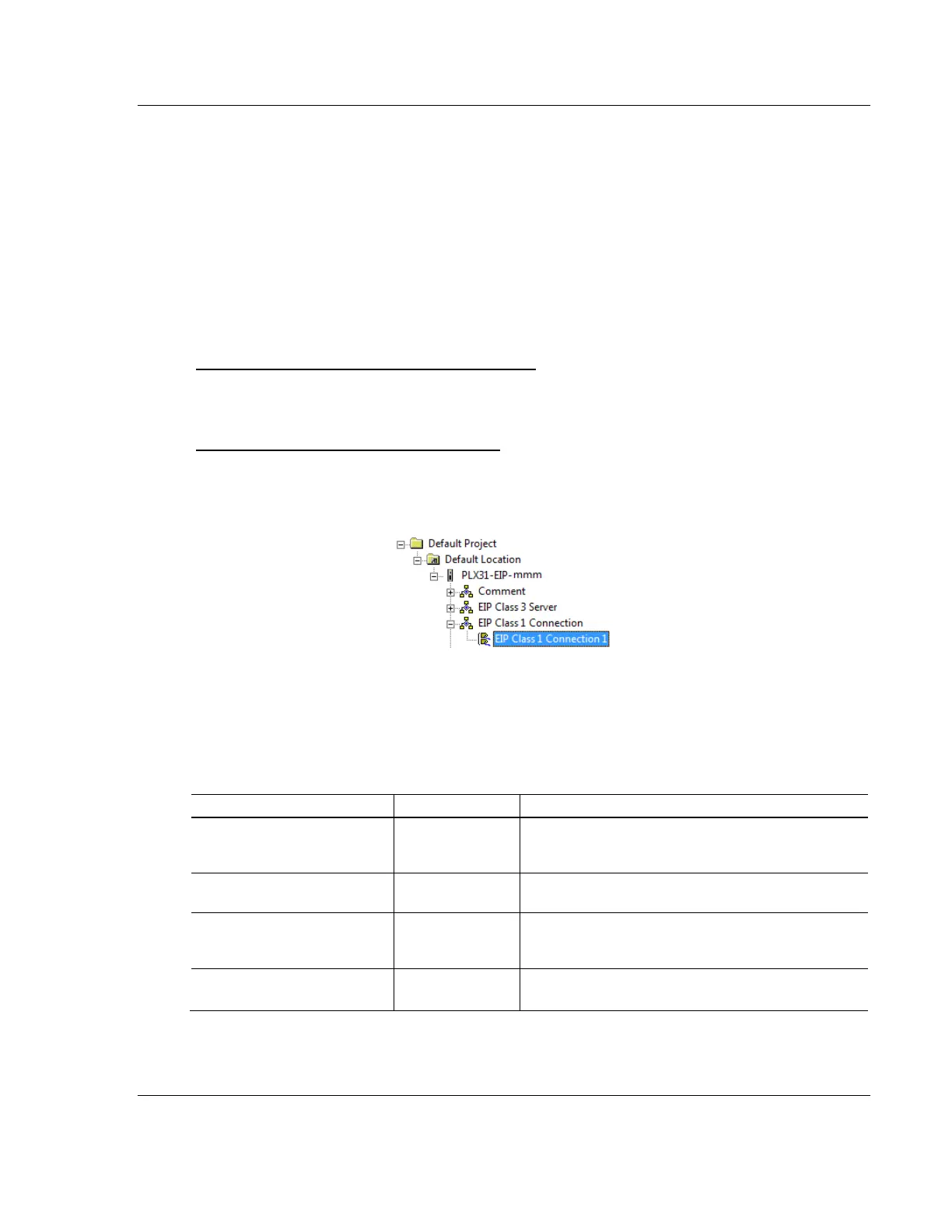
1 In ProSoft Configuration Builder, click the [+] next to the gateway, then click
the [+] next to EIP Class 1 Connection [x]. The value of [x] depends on the
number of ports on your PLX3x gateway (1 to 4).
2 Double-click the EIP Class 1 Connection [x] to display the Edit - EIP Class 1
Connection [x] dialog box.
3 In the dialog box, click a parameter and then enter a value for the parameter.
There are four configurable parameters for each I/O connection in ProSoft
Configuration Builder.
Specifies the starting address within the gateway’s
virtual database for data transferred from the gateway
to the PLC.
Specifies the number of Integers being transferred to
the PLC's input image (248 integers max).
Specifies the starting address within the gateway’s
virtual database for data transferred from the PLC to
the gateway.
Specifies the number of integers being transferred to
the PLC's output image (248 integers max).