MVI56-PDPMV1 ♦ ControlLogix Platform Configuring the MVI56-PDPMV1 Module
PROFIBUS DPV1 Master User Manual
Page 101 of 251 ProSoft Technology, Inc.
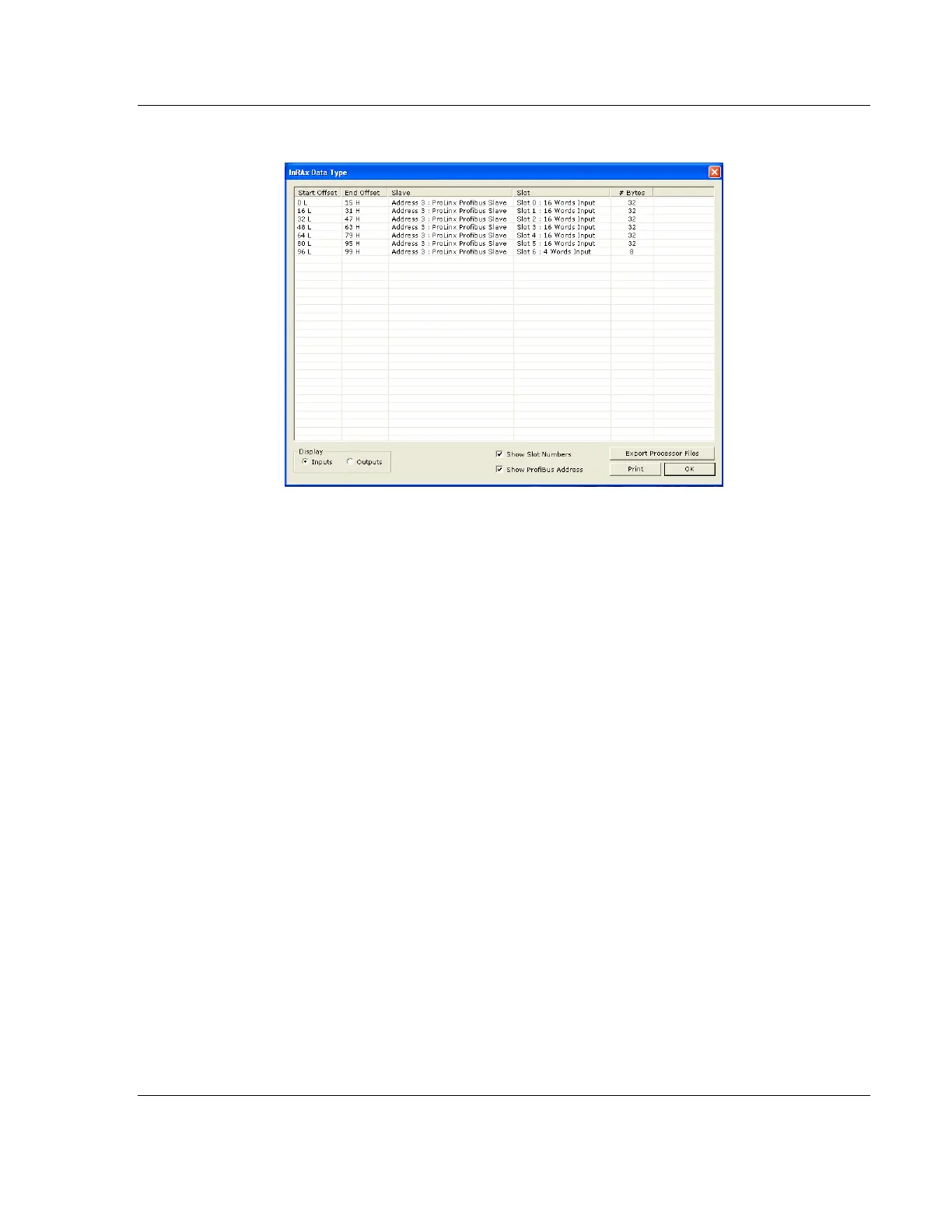
This action opens the inRAx Data Type dialog box.
2 Notice that there are buttons in the Display area of the dialog box to show
INPUTS or OUTPUTS. These Input and Output maps correspond to the Input
and Output data you configured for the Configuring the PROFIBUS Slaves
(page 85). Notice also that there are CHECK BOXES to optionally show (if
checked) or hide (if not checked) the slot numbers and PROFIBUS
addresses.
3 Click PRINT to print the input and output maps for reference. Note that you
must do this separately for each of input and output map by first clicking on
the INPUTS radio button and then the PRINT button; then, click on the
OUTPUTS radio button and then the PRINT button, again.
4 When you have finished printing the processor memory maps, you can click
OK to close the dialog box and click OK again to close the Master Setup
dialog box; or, leave them open for the next step, exporting the processor
files.
5 Keep the printed memory maps available so you can refer to them when you
configure the sample ladder logic in RSLogix. The sample ladder logic
contains input and output arrays that must be cross-referenced with the
variables.