Configuring the MVI56-PDPMV1 Module MVI56-PDPMV1 ♦ ControlLogix Platform
User Manual PROFIBUS DPV1 Master
Page 122 of 251 ProSoft Technology, Inc.
2.5.3 Viewing the Fieldbus Data from the MVI56-PDPMV1’s
Configuration/Debug Menu
Note: For this procedure, you must connect a serial cable from the serial port on your PC to the
RJ45 to DB9M adaptor cable on the MVI56-PDPMV1 module.
1 In ProSoft Configuration Builder, select the MVI56-PDPMV1 MODULE, then
click the right mouse button to open a shortcut menu.
2 On the shortcut menu, choose DIAGNOSTICS. This action opens the
Diagnostics dialog box.
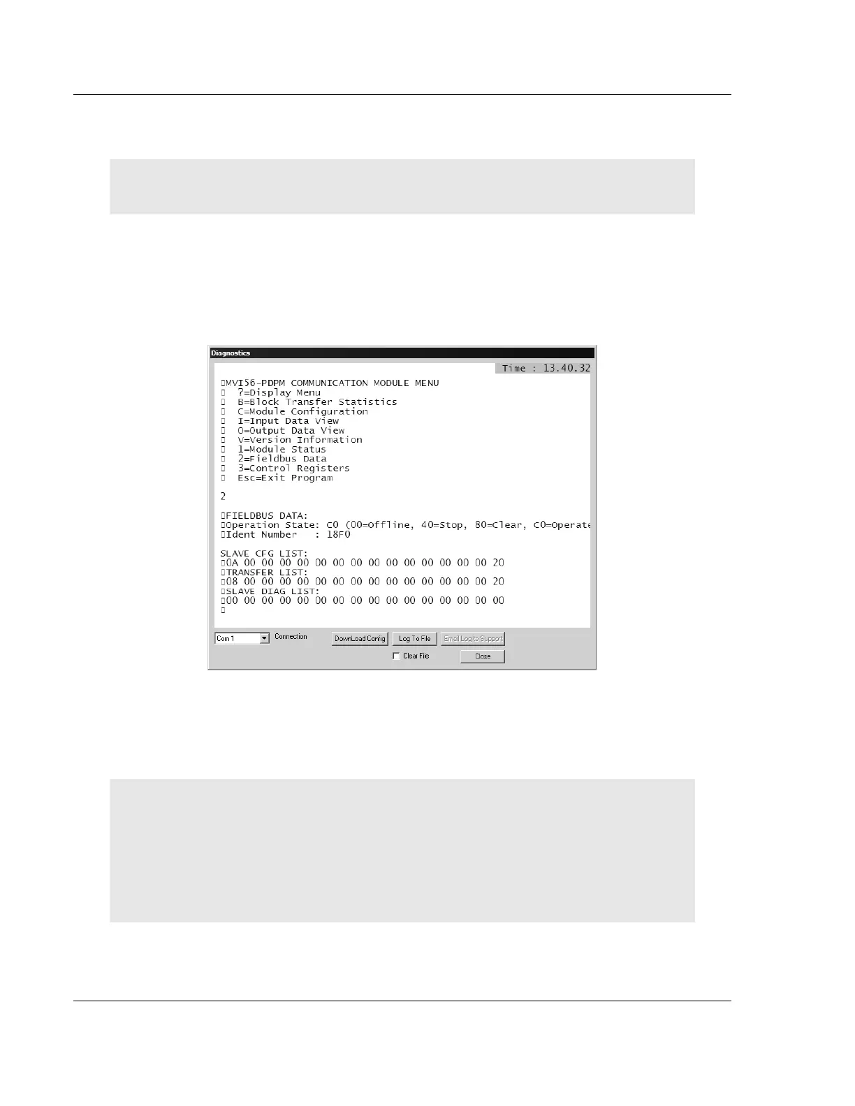
3 Press [?] to display the main menu, and then press [2] to view Fieldbus data.
4 Note the value in Operation State. If the Master and the slave are
communicating correctly, the operation state will be C0 (hex).
5 Note the values in SLAVE CFG LIST, TRANSFER LIST and SLAVE DIAG
LIST. If the Master and slave are communicating successfully, the values in
SLAVE CFG LIST will match the values in TRANSFER LIST.
Note: Each list is a hexadecimal representation of a bitmap of slave addresses on the PROFIBUS
network. In the illustration above, a value of 20h in the rightmost columns of both of the first two
lists means one slave at address 125 is configured and communicating with the Master. Notice that
the values in the leftmost columns of the first two lists do not match. This means that the slave at
address 1 is configured, but is not communicating with the Master. The slave at address 3,
however, is both configured and communicating with the Master. Below is an explanation on how
to read these bitmaps.
Each (XX XX) grouping represents one word containing 16 slave addresses.
 Loading...