MVI56-PDPMV1 ♦ ControlLogix Platform Diagnostics and Troubleshooting
PROFIBUS DPV1 Master User Manual
Page 175 of 251 ProSoft Technology, Inc.
4 Diagnostics and Troubleshooting
In This Chapter
Basic Troubleshooting Steps ............................................................... 175
LED Status Indicators: Front of MVI56 Module ................................... 175
Using ProSoft Configuration Builder (PCB) for Diagnostics................. 180
The module provides information on diagnostics and troubleshooting in the
following forms:
LED status indicators on the front of the module provide general information
on the module's status.
You can view status data contained in the module through the
Configuration/Debug port or the Ethernet port, using the troubleshooting and
diagnostic capabilities of ProSoft Configuration Builder (PCB).
You can transfer status data values from the module to processor memory
and can monitor them in the processor manually or by customer-created
logic. For details on Status Data values, see Error Status Table.
4.1 Basic Troubleshooting Steps
1 Verify that the module is installed correctly, and is communicating with the
processor.
2 Install the most current version of ProSoft Configuration Builder.
3 Note the color and behavior of the LED Status Indicators (lights) on the front
panel. Refer to the chart in the following section for examples.
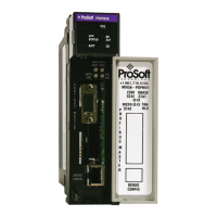
4.2 LED Status Indicators: Front of MVI56 Module
The LEDs indicate the module’s operating status. The module has two sets of
LED status indicators:
MVI56 Module Status LEDs on the front of
the module near the top
PROFIBUS Master Status LEDs behind the
door on the front of the module.