Page 52
Relays
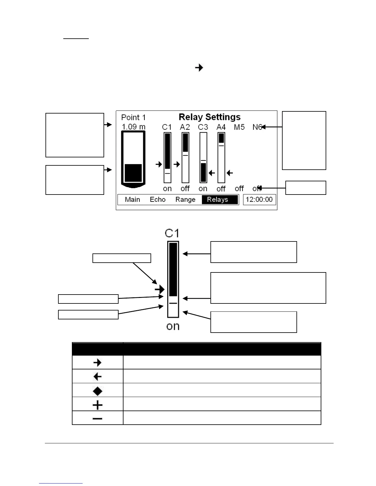
The relays screen indicates the current state of all relay outputs and gives a visual
representation of the current interface level and the on and off setpoints of the
individual relays. The level icons, e.g. “ ” (point 1), represent the level reading
of the transducer that the corresponding relay is assigned to (see table below).
Relays that do not relate to level will be displayed without the graphical
representation of level setpoints but will still show the relay number and status.
Point 1 Level, shown on left hand side of relay diagram.
Point 2 Level, shown on right hand side of relay diagram.
Average level, shown on left hand side of relay diagram.
Sum of levels, shown on left hand side of relay diagram.
Differential level, shown on left hand side of diagram.
All icons show the measurement from the vertical centre of the icon.
A = Alarm
C = Control
M = Misc.
N = Not set
The numbers
represent the
relay number
Solid region within here, relay
is always ACTIVE (ON).
Region between solid area and line
signifies relay can be ACTIVE if
triggered or INACTIVE if not triggered.
Light region within here, relay
is always INACTIVE (OFF).
Current point and
value in P104,
measurement units
shown in P100,
mode of operation
Tank view of the
level of the current
point of measure
 Loading...