Accessories
R&S
®
TS7124M
73User Manual 1525.5394.02 ─ 05
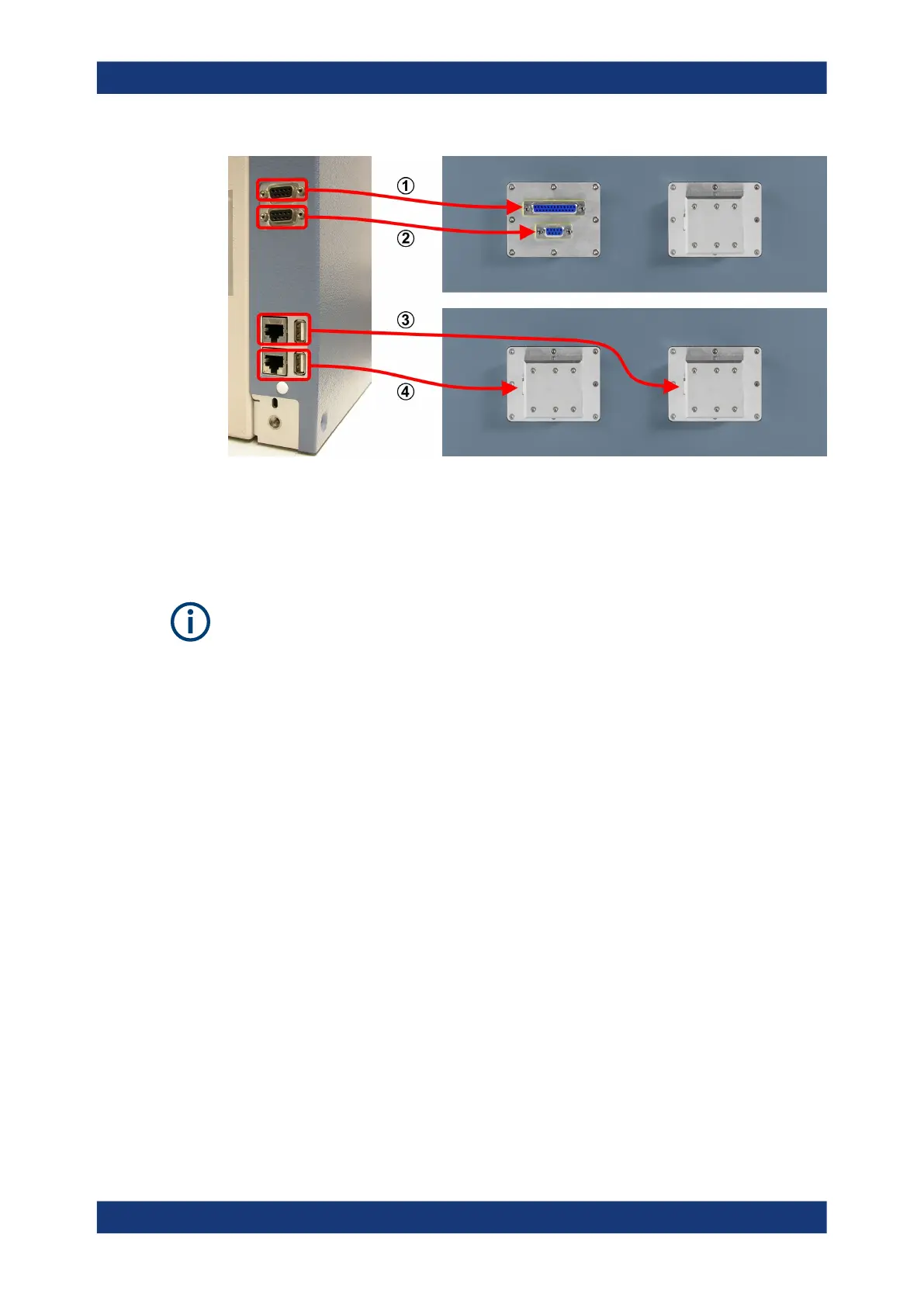
Figure 6-45: Allocations between rear connectors of the energy chain and front feedthroughs
1 = Upper rear D-Sub 9 socket is connected to front D-Sub 25 feedthrough (pins 1 to 9, only)
2 = Lower rear D-Sub 9 socket is connected to front D-Sub 9 feedthrough
3 = Upper rear LAN or USB 2.0 socket is connected to right front LAN or USB 2.0 feedthrough
4 = Lower rear LAN or USB 2.0 socket is connected to left front LAN or USB 2.0 feedthrough
If there are two LAN connections or two USB 2.0 connections in the energy chain, you
can distinguish the cables protruding from the front door by the cable length:
●
The shorter cable comes from the lower rear LAN or USB 2.0 socket and is con-
nected to the left front LAN or USB 2.0 feedthrough.
●
The longer cable comes from the upper rear LAN or USB 2.0 socket and is con-
nected to the right front LAN or USB 2.0 feedthrough.
The feedthroughs for your energy chain configuration (see Table 6-8) are factory-
mounted. However, you can still install a different feedthrough. For an instruction on
how to install a feedthrough, see Chapter 7.3, "Mounting a feedthrough", on page 76.
The trailing cable (see 2 in Figure 6-44) in the energy chain is a wear item. For exam-
ple, it can break after a high number of opening and closing cycles of the drawer. If the
trailing cable is defective, you can exchange it as described in Chapter 8.6, "Exchang-
ing the trailing cable in the energy chain", on page 156. Two spare trailing cables are
included in the delivery.
Apart from this cable exchange, the energy chain is not a serviceable part. If it is defec-
tive or not working correctly, replace it.
Energy chain R&S
TS-F24EC