Accessories
R&S
®
TS7124M
72User Manual 1525.5394.02 ─ 05
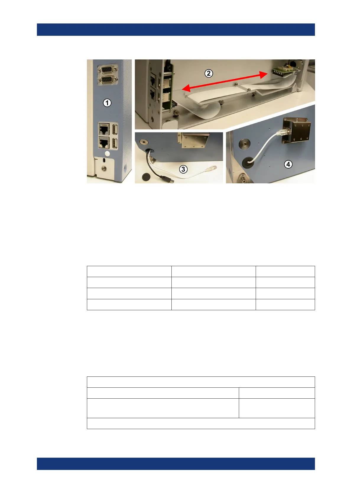
Figure 6-44: The energy chain guides cables from front feedthroughs to the rear of the chamber
1 = Rear connectors for 2x D-Sub 9 pin (on top) and below 2x Ethernet (LAN) and 2x USB 2.0
2 = View inside the opened chamber side wall (blue metal cover removed): While the drawer opens and
closes, the connector assembly (green) at the front end of the trailing cable ("energy chain") moves
along the red arrow
3 = Cable outlet (open, rubber stopper below), here with two cables mounted: short black USB 2.0 cable for
left feedthrough and longer white LAN cable for right feedthrough
4 = Cable outlet closed with the rubber stopper, here one Ethernet (LAN) cable mounted and connected to
the left feedthrough (no. 4)
Table 6-8: Combinations of two front feedthroughs, for which the energy chain can be configured:
Left front feedthrough (no. 4) Right front feedthrough (no. 5) Number of cables
D-Sub (9 pin and 25 pin *) USB 2.0 or LAN 3
USB 2.0 USB 2.0 or LAN 2
LAN USB 2.0 or LAN 2
In these configurations, the D-Sub feedthrough is always mounted in the left feed-
through opening of the front door (see Figure 7-2).
The D-Sub feedthrough has two connectors, with 9 pins and 25 pins. From both these
connectors, the energy chain guides 9-wire cables to the two 9-pin connectors at the
chamber's rear side (see 1 in Figure 6-44).
(*) Hence, the 25-pin connection of the D-Sub feedthrough is reduced to 9
pins.
Energy chain properties
Cycles (opening and closing of the drawer) before failure > 100,000
Connected pins of the 25-pin D-Sub connector
(if the D-Sub feedthrough R&S TS-F1SD259 is used)
Pins 1 to 9
For the allocations between rear and front connectors, see Figure 6-45
Energy chain R&S TS-F24EC