Configuration
R&S
®
TS7124M
93User Manual 1525.5394.02 ─ 05
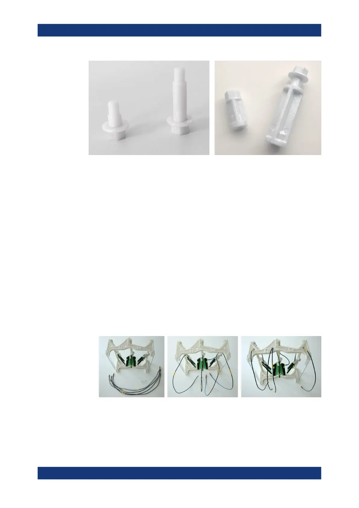
Figure 7-23: The short- and the long-distance bolt, the spacer and the long disk fixture
To mount the half antenna ring into the chamber
If not removed, also remove the top cover as described in Chapter 7.4.1, "Opening the
top cover", on page 78).
For the remainder of this procedure, remember to avoid touching the gasket that
seals the top cover.
1. If the four spacers are not installed as in Figure 7-22, remove the four round
absorber pads at the upper end of the front and rear chamber wall.
2. Screw the four spacers into the four upper positions, using a torque wrench No. 13
with a torque of 4.6 Nm.
3. Connect SMA/SMP cables of appropriate length to the SMP connectors at the
antennas.
4. Thread the cables through the holes in the half antenna ring. Make sure to thread
them to the rear side (away from the "FRONT" label).
If two cables go through the same hole, it is easier to first thread both of them
through that hole by using the cables' thinner SMP connector ends. Then connect
the cables to the antennas.
Figure 7-24: Attach the antenna cables to the antennas and thread them through the holes in the
half antenna ring
5. Fix the cables to the antenna ring bars (rails), using the cable guide clips (this
detail is highlighted in Figure 7-25 by a red circle).
Installing an antenna ring or holder
 Loading...